
Subscribe to Our Youtube Channel
Related Manuals for Elster Instromet DL210


Summary of Contents for Elster Instromet DL210
- Page 1 Data Logger DL210 DL210 Data Logger DL210 Operating Manual and Installation Instructions Operating Manual: 73018816 SW version: from V1.00 Issued 18.09.2006 (a) Edition:...
- Page 2 Data Logger DL210 Elster-Instromet GmbH...
- Page 3 Data Logger DL210 All rights reserved. Copyright © 2006 Elster-Instromet GmbH, D-55252 Mainz-Kastel All details and descriptions in this operating manual and installation instructions have been given only after careful checking. Despite this however, the possibility of errors cannot be completely eliminated.
-
Page 4: Table Of Contents
Input 2 is signalling input (unmodifiable ) ............37 3.1.5 Description of the values................37 3.1.6 Submenu encoder data................. 42 3.2 Archives in the DL210 ..................44 3.2.1 Values common in all archives ..............45 3.2.2 Structure of the month archive Input 1 ............46 3.2.3... - Page 5 3.6.1 Description of the values ................83 3.6.2 Optical interface (Interface 1) ................87 3.6.3 Modem operation in the DL210 (Interface 2) ..........87 3.6.4 Short messages in the DL210 (SMS function)..........88 3.7 User list.........................95 4 Operation under calibration ................97 4.1 Setting the parameters on site ................97 4.2 Checking the set values..................97...
- Page 6 5.4.3 Battery service life..................115 Appendix ......................118 Appendix A: Approvals .................. 119 EC Declaration of Conformance for DL210 ............119 Appendix B: Technical data ................121 B-1 General data (mechanical) ................. 121 B-2 Power supply...................... 121 B-3 Encoder, pulse and message inputs ..............122 B-4 Optical interface ....................
- Page 7 Data Logger DL210 Safety instructions The connections of the DL210 are freely accessible during setting up. In order to avoid damage to the components, make sure that no electrostatic discharge (ESD) can occur. The person carrying out the installation can, for example, discharge himself/herself by touching the potential equalisation line.
- Page 8 Data Logger DL210 Items supplied and accessories II-1 Included items The following items are included with the DL210: a) Data Logger DL210 b) Dispatch list c) Design data sheet d) Operating Manual e) Bag of accessories II-2 Ordering information and accessories Data Logger DL210 ·...
- Page 9 Data Logger DL210 Elster-Instromet GmbH...
- Page 10 Data Logger DL210 Elster-Instromet GmbH...
-
Page 11: Part 1
Data Logger DL210 Part 1 Device description relevant to calibration Elster-Instromet GmbH... -
Page 12: Brief Description
Data Logger DL210 1 Brief description 1.1 Functions and performance features General remarks: The Data Logger DL220 is intended as a battery operated, compact device, capable of being calibrated, for the acquisition and storage of counting pulses or encoder readings as well as level changes for various types of energy: ·... - Page 13 Data Logger DL210 Pulse / signalling inputs: · Input 1 programmable as pulse, signalling or encoder input (Namur, SCR) . · Input 2 permanently configured as signalling input. · Possible connection of reed contacts and transistor switches on both inputs.
- Page 14 Sending short messages (SMS): · Ten different brief messages via SMS to a control station with GSM modem or a mobile phone based on messages occurring in the DL210. · Sending of an SM to up to two recipients possible.
-
Page 15: Operation
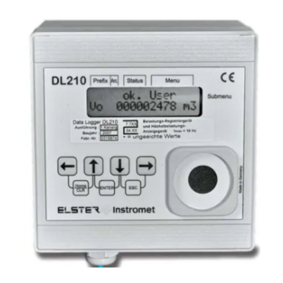
Data Logger DL210 2 Operation 2.1 Front panel For operation a two-line LCD display with 16 places per line and four cursor keys is provided on the front panel: DL210 Status Menu Prefix Arc. Submenu Data Logger DL210 Belastungs-Registriergerät und Höchstbelastungs-... -
Page 16: Display
Data Logger DL210 2.2 Display Basic layout of the display: Prefix Archive Device status M e n u m a x á A W B I n p u t 1 à Submenu V b P 1 2 3 4 5 6 7 . 8 Both lines in the display are subdivided into fields which are described below. - Page 17 Data Logger DL210 Meaning of the letters: "Alarm" At least one status message has occurred which is valid as an alarm. Alarm messages are copied into the status register and are retained here, even after rectification of the cause of the error, until they are manually cleared.
-
Page 18: Operation
Data Logger DL210 2.2.2 Line 2 = Value with name and unit In the second line the name, value and (when available) the unit of the data are always shown. Uncalibrated values are identified for the user with an asterisk ("... -
Page 19: Meaning Of The Keypad
Data Logger DL210 2.3.2 Meaning of the keypad The meaning of the keypad depends on whether only values are being recalled (operation – highlighted in colour) or whether the DL210 is located in the input mode (shown in italics): Moves to left... -
Page 20: Formation Of The List Structure
Data Logger DL210 2.4 Formation of the list structure The data display in the DL210 is structured in a tabular form. The individual columns in the table each contain associated values. 2.4.1 Summary charts, List Structure (1) Input I1 is counter input Input I1 is signalling input Û... -
Page 21: Summary Charts, List Structure (2)
Data Logger DL210 2.4.2 Summary charts, List Structure (2) Input I1 is encoder input Input I2 is signalling input Original counter reading Û Û St.I2 Status of signal input I2 (encoder) Main counter I1 MdMI2 Mode for monitoring I2 I1 to I2 to "I2"... -
Page 22: Summary Charts, List Structure (3)
Data Logger DL210 2.4.3 Summary charts, List Structure (3) Status System Û Û Û SReg Total status register Time Time and with "® " to date Stat Total momentary status MdTim Summer / winter time on/off "I2" « Service» Clear total status register... -
Page 23: Summary Charts, List Structure (4)
Data Logger DL210 2.4.4 Summary charts, List Structure (4) Interface User Û Û Û GSM.N Network operator User Value 1 GSM.L GSM reception level User Value 2 "Service" Modem status User Value 3 "Input 1" P.Sta Status PIN of SIM card (GSM) -
Page 24: Summary Charts, Submenus "U1" To "U9
Data Logger DL210 2.4.5 Summary charts, Submenus "U1" to "U9" Note: Meaning of the abbreviated designations: See Chapter 3 and Appendix C: Submenu: "Max. measurement period counter I1" TIME (Date) Û Û Û to Date to TIME Submenu: "Max. day counter I1"... -
Page 25: Changing Values
The methods of changing values differ depending on the value. These are therefore subdivided into so-called "data classes". Each value in a data class is treated identically on entry. The following data classes are present in the DL210: Type Description Change via "ENTER"... -
Page 26: Entry Function
Data Logger DL210 2.5.2 Entry function Depending on the data class slight differences exist for the entry of values. The following points are the same for all data classes: · ENTER activates the entry mode (appropriate numbers flash) and terminates the entry of a value with acceptance of the valid value. -
Page 27: Entry Errors
Data Logger DL210 Action Function HOME/CLR No function. Entry not possible (e.g. archive values) ENTER in archive: initiation of the skip function (see Chap. 3.2.5.2). Data class not present. ENTER Branching occurs to the appropriate submenu after ENTER. ENTER Return from the submenu into the main menu. - Page 28 Data Logger DL210 2.5.4 Example of changing values "Adjustable counter" on Input 1 is to be changed (short designation: V1.A): Select Input 1 with the keys I n p u t 1 7 6 5 4 3 2 1 . 0...
- Page 29 Data Logger DL210 Through simultaneous pressing of the key (function "HOME/CLR") the I n p u t 1 value (e.g. a counter reading) V 1 A * 0 0 0 0 0 0 0 . 0 can be reset directly to its default value ("0").
-
Page 30: Securing The Values (Access Rights)
2.6 Securing the values (access rights) Within the DL210 a setting can be made for each existing value of whether it can be read and/or written by the appropriate access parties. This enables the DL210 to be used in a very flexible manner. -
Page 31: Supplier And Customer Locks
Data Logger DL210 supplier's lock open. If the PTB logbook is full, these parameters can only be changed with the calibration lock open. With a full PTB logbook an open calibration lock cannot be closed. In this case the PTB logbook must first be deleted (see Chap.: 3.3.1)! 2.6.3 Supplier and customer locks... - Page 32 Data Logger DL210 Opening the supplier's lock To open the lock the key must be pressed once more so that the following display appears: o k . S e r v . C o d . S Press the keys simultaneously (skip to entry function).
- Page 33 Data Logger DL210 Changing the supplier's lock If the supplier's lock is open, a new supplier's combination is entered under the display: o k . S e r v . C o d . S in the same manner. To do this, press the keys simultaneously (skip to entry function).
-
Page 34: Opening, Changing And Closing The Customer's Lock
Data Logger DL210 2.6.5 Opening, changing and closing the customer's lock The customer's lock is located in the "Service" list. The procedure for opening, changing and closing corresponds to that of the supplier's lock. Here, the following displays are recalled: Display of the status and closing of the customer's lock: o k . -
Page 35: Functional Description
Data Logger DL210 3 Functional description The data display is structured in tabular form (list structure) (see Chapter 2.4). The individual columns in the table each contain associated values. The following functional description is orientated to this list structure. 3.1 List structure for Input 1 and Input 2 3.1.1 Input 1 set as counting input... -
Page 36: Input 1 Set As Encoder Input
Data Logger DL210 3.1.2 Input 1 set as encoder input Name Address Designation / value Cal. Access Default 1:240 Original counter, Input 1 (encoder counter) 1:200 Main counter input 1 V1.A 1:203 Adjustable counter, I1 1:210 Flow rate I1 L.MI1... -
Page 37: Input 1 Set As Signal Input
Data Logger DL210 3.1.3 Input 1 set as signal input Name Address Designation / value Cal. Access Default St.I1 1:228 Status I1 Md.I1 1:207 Mode I1 Md.MI1 12:157 Mode for monitoring I1 SC.I1 12:154 Source for monitoring I1 1:0160 Var. - Page 38 Here is defined which message in the status register of the input appears when the set limit is infringed. Md.I1 Mode, signal input I1 . The signal input 1 of the DL210 can be assigned with various input modes. The following modes are realised: “0”...
- Page 39 Data Logger DL210 MdMI1 Mode for monitoring Input 1 MdMI2 Mode for monitoring Input 2 Various modes for monitoring can be programmed. The following modes are possible: Mode for monitoring Explanation Switched off No monitoring > L.MI1 Limit exceeded (value > L.MI1) ³...
- Page 40 Elster-Instromet Evaluation Software WinVIEW, a so-called "DS-100 number" is needed for each counter. This number is pre-assigned at the factory based on the fabrication number of the DL210 and does not need to be changed. DS.Cb DS-100 number, Counter V1.A See "DS.Ca"...
- Page 41 The following other values are also available for Input 1: Measuring point designation to AA Address: 1:221 A 33-place designation of the measuring point can be saved in the DL210. As a result, the requirements of the Association Agreement (AA) can be optimally considered. Unit Address: 1:208 Each input can be assigned a unit (default: "m3") which is composed of five characters...
-
Page 42: Submenu Encoder Data
Data Logger DL210 3.1.6 Submenu encoder data Under "Z.Dat" skipping into the submenu: "Encoder data" can be made with "ENTER" (press arrow keys simultaneously). The data provided by the encoder can be seen in this submenu. The single entries can be called with the keys . - Page 43 Maximum encoder flow Permissible flow maximum for plausibility check. BdEnc Encoder baud rate The baud rate for the transfer of data from the encoder to the DL210 can be set here, deviating from the standard, for special applications. SN.E Encoder serial number The encoder serial number (only for encoders with interface "SCR EDIS 95").
-
Page 44: Archives In The Dl210
Data Logger DL210 3.2 Archives in the DL210 There are six different types of archive in the DL210: a) Measurement period archive b) Day value archive c) Month archive d) Logbook e) Changes archive f) PTB logbook Apart from the PTB logbook all archives are structured as a ring buffer memory, so that the latest data is always available. -
Page 45: Values Common In All Archives
They CANNOT be used for billing! Checksum of a data record In the DL210 a checksum is appended to each data record to ensure that the data is transferred correctly. Here, two errors are certain to be detected and one error can also be corrected (CRC-16 procedure). -
Page 46: Structure Of The Month Archive Input 1
V1 and V1.A (see below) and the day and measurement period maxima found by the DL210 are retained (high-flow display function). They are saved for the last 15 months and can be used for billing purposes. - Page 47 Data Logger DL210 Meaning of the displayed values: ABNo Internal archive block number Time Time of saving (at end of month) Time Date of saving (at end of month) Counter V1 Calibrated counter V1 Counter reading of the counter at the time of saving.
-
Page 48: Structure Of Meas. Period And Day Value Archives Input 1
V1 or V1.A) are determined for the display in the DL210 or calculated by the evaluation software based on the differences in counter readings. The measurement period and day value archive are only available for Input 1 in the pulse or encoder mode. -
Page 49: Measurement Period And Memory Depth
When setting the measurement period it is essential to take into account the DL210 "measurement cycle". See "MCyc" in Chapter 3.4.1. For Input 1 the following memory depth occurs for 11500 archive rows (without additional messages which are held in the archive): Measurement period MP.I1 in minutes... - Page 50 Data Logger DL210 3.2.5.1 Display of counter increment (flow value) The entries of the measurement period archive can be called into the display. Here the increments of the counters in comparison to the corresponding previous entry are also included. They are identified with a "D". Normally, with a counter increment the flow (consumption) within a measurement period is involved.
-
Page 51: Application As High Flow Display Device
The current and last saved values can be called up via the DL210 display. At the end of each month the counter reading and the highest of these two flow values for the input are saved in the corresponding month archive. -
Page 52: System Interface
3621234 "a" and "b") can be saved in each of the two archives. These are set in the DL210 as default at the factory with the main counter "V1" and the adjustable counter "V1.A". Since the evaluation software must differentiate between the two counters, each counter is unambiguously identified based on †... - Page 53 Data Logger DL210 In the following the above mentioned relationships are listed with reference to the representation in the DL210, in the AS-200 and in WinPADS or WinCOMS software. Archive DL210 Counte DS-100 Input Designation Archive content display number Month-end reading of the...
-
Page 54: Reading Out Archives
Data Logger DL210 3.2.8 Reading out archives There are a number of ways of reading out the above mentioned archives in the DL210: · AS-200/S2 (from version V8.4) on site. At the time of printing this operating manual the day value archive of the DL210 cannot yet be read out! ·... - Page 55 In order that a readout can be carried out based on the readout notes, these must first be set in the DL210. This can be done easily with WinPADS for the DL200 series or with the AS-200. Here is defined whether an appropriate archive is to be read out and in which time period.
- Page 56 In order that an automatic readout can be carried out based on the readout notes, these must first be set in the DL210. This can be done easily with WinPADS for the DL200 series or, with restriction, the AS-200. Here is defined whether an appropriate archive is to be read out and in which time period.
-
Page 57: Status List
3.3.1 Description of the values S.Reg Status register In this status display all group status messages which have occurred in the DL210 since the last deletion are displayed in the form of message number(s). If they are no longer applied, they can be cleared under "Clr" (see below). For the display of the individual status messages this display item is also realised as a method of entry into a submenu for further messages (see submenu Status register). -
Page 58: Submenu: Status Register
Data Logger DL210 PLogb PTB logbook The PTB logbook contains the values which have been changed with the calibration lock closed and the supplier's lock open. If the PTB logbook is full, these values can only be changed with the calibration lock open. -
Page 59: Submenu: Logbook
Data Logger DL210 3.3.4 Submenu: Logbook The logbook is a chronological listing of all events which can occur in the DL210. Each change leads to a corresponding entry in the logbook: · Signal "arrives" Display "↑" · Signal "goes" Display "↓"... -
Page 60: Submenu: Changes Archive (Audit Trail)
Data Logger DL210 3.3.5 Submenu: Changes archive (audit trail) The changes archive (termed "Audit trail" at Elster-Instromet) contains the last 200 changes made in the device. This includes parameter changes and also opening and closing the locks. The value before (old = "a") and after the change (new = "n") is retained... -
Page 61: Submenu: Ptb Logbook
Data Logger DL210 3.3.6 Submenu: PTB logbook The PTB logbook contains the last 50 changes made to parameters which are subject to the access right "PL" (see Functional description, operating lists, Chapter 3). Changes to these parameters may only be carried out with the supplier's lock open. Changes made with the calibration lock open are not considered in the PTB logbook. -
Page 62: Description Of Values Shown In The Audit Trail And Ptb Logbook
Data Logger DL210 3.3.7 Description of values shown in the audit trail and PTB logbook ABNo Internal archive block number This is a number (constant from 1 to 65535) which is used as a label for one data record (corresponds to one row) in the archive. For the first time of saving the block number 1 is issued, then 2 etc. -
Page 63: The Status Register
(usually time modes). 3.3.8.2 Status register and momentary status The status display in the DL210 is subdivided into two ranges: One is the "momentary status" which contains only the current messages. The messages: Alarm, Warning and Report are entered in this register. If the cause of a message is no longer active, it is automatically deleted from this register. -
Page 64: Summary Of Message Numbers
Data Logger DL210 3.3.9 Summary of message numbers Momentary Stat St.Sy St.1 St.2 St.3 St.4 status Status S.Reg SR.Sy SR.1 SR.2 SR.3 SR.4 register Type Group System Status 1 Status 2 Status 3 Status 4 message message Restart Enc.Plaus. message 01 Enc.Error... -
Page 65: Explanation Of The Messages
Batt. low The notice appears when the remaining battery service life computed by the DL210 has fallen below the limit of 3.0 months. Clock n. set The correction factors needed for the internal clock are not correct or have not yet been entered. - Page 66 Data Logger DL210 Status messages Status 1, Status 2, Status 3 und Status 4 Enc.Plaus. The set encoder flow rate has been exceeded. Enc.Error The connected encoder is not supplying any data. I1 Warn Lim. A set warning limit on Input I1...2 has been violated.
-
Page 67: Determining An Error Message
The following describes the procedure of interpreting a message in the display and how it can also be cleared. The following case serves as an example: What should be done ? "The symbol "W" in the DL210 is on (continuously lit)". With the key select the S t a t u s →... -
Page 68: Clearing An Alarm Or A Warning
Data Logger DL210 3.3.12 Clearing an alarm or a warning The clearing of all past (!) messages in the status register S.Reg occurs in the list "Status" under the display: "Clr". Clearing messages is only possible with an open calibration, manufacturer's or supplier's lock. -
Page 69: Events In The Dl210
- manual triggering of data backup using "Save" in the service list. The individual columns in the following table have the following meaning: Display: Plain text of status messages and events in the DL210 display. Event: Name of the triggering event. - Page 70 Data Logger DL210 Display Event Keypad entry Interface Description 0B02 12_02:1.0 ends Limit.I2¯ Message 12 I2: Limit violated in St.2 2B02 12_02:1.1 starts Limit.I2- 13_01:1.0 0C01 ends RepSig.I1¯ Message 13 I1: Report signal active in St.1 13_01:1.1 2C01 starts RepSig.I1- 13_02:1.0...
- Page 71 Data Logger DL210 Display Event Keypad entry Interface Description Group messages of all single and system messages (St.Sy, St.1, St.2, St.3, St.4) 01_01:2.0 1001 ends Message1¯ Message 1 in Stat Status message 1 Message1- 01_01:2.1 3001 starts Message2¯ 02_01:2.0 1101...
- Page 72 Data Logger DL210 Display Event Keypad entry Interface Description 4401 1,05_01:1.0 ends ST.1:M1-5¯ Message 1-5 Any message between 1 in St.1 and 5 in St.1 6401 1,05_01:1.1 starts ST.1:M1-5- 1,05_02:1.0 4402 ends ST.2:M1-5¯ Message 1-5 Any message between 1 in St.2 and 5 in St.2...
- Page 73 Data Logger DL210 Display Event Keypad entry Interface Description Any message 1,13_03:1.0 4C03 ends ST.3:M1-13¯ Message 1-13 between 1 and 13 in in St.3 ST.3:M1-13- 1,13_03:1.1 6C03 starts St.3 Any message ST.4:M1-13¯ 1,13_04:1.0 4C04 ends Message 1-13 between 1 and 13 in in St.4...
- Page 74 Data Logger DL210 Display Event Keypad entry Interface Description 5A02 1,11_02:2.0 ends St.Sy:M1-11¯ Message Any message between 1 1...11 in St.Sy and 11 in St.Sy 7A02 1,11_02:2.1 starts St.Sy:M1-11- 1,13_02:2.0 5C02 ends St.Sy:M1-13¯ Message Any message between 1 1...13 in St.Sy and 13 in St.Sy...
- Page 75 Data Logger DL210 Display Event Keypad entry Interface Description 5F01 1,16_01:2.0 ends Stat:M1-16¯ Message Any message between 1 1...16 in Stat and 16 in Stat 7F01 1,16_01:2.1 starts Stat:M1-16- Keypad Display Event "Interface" Description entry Programmed events Arose again ¯...
- Page 76 Data Logger DL210 Keypad Display Event "Interface" Description entry Data change (e.g. change of counter reading or time) Value change¯ 8201 After change Change of Value for month archive 1 archive was changed 8301 Before change Value change ¯ Value for...
-
Page 77: System List
Changeover from winter to summer time: 1:4A0 Changeover from summer to winter time: 1:4A8 The details must be given in the format: "yyyy-mm-dd,hh:mm:ss". With a change of the mode, the time in the DL210 is automatically corrected and should therefore be checked. Elster-Instromet GmbH... - Page 78 No automatic selection. AUT.V x Display switchover after x minutes. Device number DL210 The 12-place device number of the DL210 is displayed. The details correspond to the name-plate on the front membrane. Vers Version of the application software The version of the application software is displayed.
-
Page 79: Service List
Data Logger DL210 3.5 Service list Name Address Designation / value Cal. Access Default Bat.R 2:404 Remaining battery service life Bat.C 1:1F3 Battery capacity 13.0 Ah VBatM 4:410 Battery voltage of GSM modem St.SL 3:170 Supplier's lock status / close Cod.S... - Page 80 20 % of the capacity specified by the manufacturer should be subtracted to ensure that the battery is not prematurely discharged. For the standard operating mode of the DL210 (Md.I1=1, MP.I1=60, MCyc=900) this means: Battery identity number: 73015774 -->...
- Page 81 Adj.T Clock adjustment Displays the clock correction value. Through the reciprocal the number of seconds can be established for the interval after which the DL210 automatically subtracts or adds 1 second to compensate the inaccuracy of the clock crystal. It should be noted that the ambient temperature of the device has a very large influence on the clock accuracy.
- Page 82 Data Logger DL210 Clr.X Execute restart With this function the DL210 can be reset to a defined initial status. The DL210 is completely cleared and "forgets" all settings (comparable to Format c:\ with a PC!) and the values in the archives.
-
Page 83: Interface List
3.6.1 Description of the values GSM.N Display GSM network operator When using the GSM modem the network operator, in whose network the DL210 has logged in, is displayed in plain text. This display is also a way of ensuring that the DL210 is logged into the GSM network. - Page 84 PIN is incorrect Entry of PIN for a SIM card In the DL210 operation of a SIM card using the PIN is supported. This means that the card can be secured against theft or it being used further. Entry takes place concealed (as for example with the entry of the supplier's lock, see Chap.
- Page 85 The call windows 1 and 2 are conceived in order to be able to only establish a connection to the DL210 at certain times during battery operation. Outside of these windows a connection is only established with an external voltage supply and an appropriately configured time window 3 or 4.
- Page 86 To send the message the entry mode is called with the key "ENTER" and the number of the event from the event list is entered on the base of which the message is to be sent. The DL210 then sends the message. In this way, the function of the settings made can be tested.
-
Page 87: Optical Interface (Interface 1)
Optionally a suitable programming cable (Elster-Instromet identification number: 73017970) can be used to be able to establish a connection within the terminal compartment of the DL210 via the X2 plug when the DL210 is supplied without an optical interface. 3.6.3 Modem operation in the DL210 (Interface 2) Depending on the version, the DL210 has an integrated GSM or GSM/GPRS modem. -
Page 88: Short Messages In The Dl210 (Sms Function)
DL210 at the end of the month. With the DL210 SMs can be sent to mobile phones or to a control room equipped with a GSM receiver and an SM reception program (e.g.: dmail). Up to five different recipient and up to three different provider telephone numbers can be saved in the device. - Page 89 · Content which is defined in the DL210. The header information consists of the phone number of the SM sender (DL210) and the time/date of reception of the SM at the SMS centre. The recipient of the SM is shown these automatically.
- Page 90 Data Logger DL210 a) User-defined messages (free layout) Address: 1:750 to 10:75E Up to ten "free" messages can be defined, each consisting of up to 15 variable values (measurements, parameters, etc.). The addresses of the values to be transferred are set to define the message.
- Page 91 - The counter entered here must be present in the measurement period archive. In the DL210 as supplied the readings of the main counter "V1" and of the adjustable counter "V1.A" are recorded in the measurement period archive "ArMP1" according to Chapter 3.2.3 (page 47).
- Page 92 Data Logger DL210 Possible (practicable) entries > Address Meaning Entry Meaning 15:750 Counter reading 1:0200 Main counter 1:0203 Adjustable counter 1:0240 Original counter (with connected encoder) 15:751 First capture value 3:0161 Max. measurement period consumption 4:0161 Max. day consumption 15:752 Time stamp for 3:0165 Time of max.
- Page 93 To send an SM, the event must be defined due to which the SM is to be sent. Description of the events: See Chap. 3.3.13. SMS mode Address: 1:D01-10:D01 In the DL210 it is possible to send an SM to up to two different recipients. This is set in the "SMS mode": Value Meaning No SM transmission SM to Recipient 1;...
- Page 94 In order to relieve the recipient of regular short messages within an interconnection of devices, it is possible in the DL210 to delay the sending of an SM depending on the device. The delay range corresponds in this respect to the maximum desired delay in minutes.
-
Page 95: User List
The setting of the values to be displayed occurs by entering the addresses of the values to be displayed with the parameterisation software "WinPADS" - "Configuration", "Display" under the addresses "1:1C2" to "12:1C2". With Menu the complete display structure of the DL210 can be switched between "complete" and "simple". Menu =... - Page 96 Data Logger DL210 Menu = 1 corresponds to the standard setting which is described in this manual. With the setting Menu = 2, the display is limited to the column "User" described here. All other columns cannot be called. Table for documenting one's own user list entries: Name Address Designation / value Cal.
-
Page 97: Operation Under Calibration
(Tel.: 06134 / 605-123 or at support@elster-instromet.com). In the rating data book the associated parameters are clearly described by quoting the address. Values not directly available in the DL210 display can be called in the Service list under the "User-specific value" (see Chap. 3.5). -
Page 98: Sealing
Once all values subject to calibration have been changed, the calibration lock is closed by pressing the button or by operation on the DL210 ("St.PL" in the "Service" list) (the symbol "P" goes out) and the opening is sealed with an adhesive label. -
Page 99: Seal Layout
Data Logger DL210 4.5 Seal layout DL210 Status Menu Prefix Arc. Submenu Data Logger DL210 Belastungs-Registriergerät und Höchstbelastungs- xxxx 2006 Baujahr/Year: Anzeigegerät fmax = 10 Hz Fabr.Nr./Ser.No: 320xxxx xx.xx Main stamp * = ungeeichte Werte HOME ENTER Pin 1 X9 X10... -
Page 100: Recalibration Of The Dl210
Data Logger DL210 4.6 Recalibration of the DL210 When using the DL210 in applications subject to official calibration, the recalibration periods should be observed. According to the Calibration directive – General regulations, issued in 2000, these recalibration periods are given in Appendix B (Special validity periods for calibration) under the following item number: 7.11 Additional equipment for gas measurement devices with the exception of the... -
Page 101: Part 2
Data Logger DL210 Part 2 Description of the Initial operation Elster-Instromet GmbH... -
Page 102: Installation
Data Logger DL210 5 Installation The DL210 is normally 106 mm intended for mounting on a wall. After removal of the two covering strips and opening the housing cover, the holes for wall mounting become accessible The drilling dimensions can be taken from the adjacent illustration. -
Page 103: Mounting Options
Data Logger DL210 5.1 Mounting options In addition, the following options can be obtained for mounting the DL210: Designation Order number Drawing 13.5 Wall-mounting bracket 04195035 Control panel mounting 04195064 frame Top-hat rail holder 04195063 Pipe mounting (universal retaining angle... -
Page 104: Antenna Options
Data Logger DL210 5.2 Antenna options 5.2.1 Option: External antenna An external antenna must be used to be able to use the integrated GSM modem: · GSM antenna, external 4m (Order no.: 730 18 956) · GSM antenna, external 10m (Order no.: 730 18 957) -
Page 105: Installation Procedure
(cable length in the DL210: approx. 15 cm). Antenna for GSM modem The DL210 is supplied as standard with an integral GSM antenna. If connection of an external GSM antenna is required, the antenna cable is passed into the housing via the upper right cable glands. - Page 106 Data Logger DL210 Fitting the SIM card Insert the SIM card, enabled for data transmission, into the SIM card holder. A card with PIN interrogation can be used. F The card must be pushed in with contacts upwards. Do not touch the contacts with the fingers.
- Page 107 Data Logger DL210 10. Connecting the modem batteries The modem battery is connected to X12 after inserting the SIM card. If a second modem battery is used, it should be connected to X13. When using two batteries, it is essential to ensure the same type and batch (adhesive label: BMT week / year) and to only change both batteries simultaneously.
-
Page 108: Terminal Layout
Data Logger DL210 5.3.2 Terminal layout Modem Batteries 2 and 3 (X12, Battery 1 programming X13) for supplying the Programming (X9 or X10) for plug (for service GSM-Modem connection X61 Clock test supplying the only) (for service only) connection (for... -
Page 109: Settings For Modem Operation
WinPADS200-DL program. The default setting is monthly. 3. Setting the parameters for SMS (messages) The DL210 offers the possibility of programming various events which result in the sending of an SMS irrespective of the set time windows (see Chapter 3.6.4 ). Also in this case, the more often such a message is sent, the shorter is the service life of the modem battery. -
Page 110: Functional Testing
With a connected meter with a pulse output the pulse transfer from the meter to the DL210 must the tested for proper function. If an encoder counter is connected, the correct transfer of the encoder counter reading must be checked. -
Page 111: Setting For Interfacing To Winview & Winlis Evaluation Software
5.3.6 Setting for interfacing to WinVIEW & WinLIS evaluation software Some settings must be made for the correct interface to the Elster-Instromet evaluation software, WinVIEW. They can be set via the keypad on the DL210, using the AS-200 or via the WinPADS software:... -
Page 112: Maintenance
5.4.1 Battery replacement (basic unit) During operation a check must be made from time to time of whether the battery needs to be replaced. A display of the remaining battery service life is provided for this in the DL210 under the list "Service". - Page 113 DL210 can take place. After starting, the DL210 should start with "Init Device" and "Reset Database". After the start the DL210 signals a voltage failure (Error code "3") and the following values must be re-entered: Supplier's lock is closed; for opening see Chapter: 2.6.4 ).
-
Page 114: Battery Replacement (Modem Battery)
During operation a check must be made from time to time of whether the modem battery needs to be replaced. A display of the modem battery voltage (VbatM) is provided for this in the DL210 under the list "Service". If this voltage is below 3.4V, the modem battery must be replaced. -
Page 115: Battery Service Life
GSM network variations. The figures assume that for the DL210 (basic unit) the standard battery (order no. 730 15 774) is used. - Page 116 Data Logger DL210 Weekly readout Readout duration 15 minutes per week, additionally 1 SMS per month Readout time window (hours per week) DL210 11.8 11.8 11.8 11.6 11.6 11.6 11.5 11.4 11.2 Modem (1 battery) Modem (2 batteries) 10.4 14,0...
- Page 117 Data Logger DL210 Sending SMS's Readout time window 1 hour per month, additionally 30 minutes per month readout SMS's per day DL210 12.5 12.0 11.8 11.5 10.9 10.4 9.9 Modem (1 battery) Modem (2 batteries) 12.2 10.0 14,0 DL210 Modem (1 Batterie)
-
Page 118: Appendix
Data Logger DL210 Appendix Elster-Instromet GmbH... -
Page 119: Appendix A: Approvals
Data Logger DL210 Appendix A: Approvals A-1 EC Declaration of Conformance for DL210 Elster-Instromet GmbH... - Page 120 Data Logger DL210 Declaration of Conformance (Translation of original document) according to the Directive 89/336/EEC of the Council of 3rd May 1989 and the changes 392L0031, 393L0068, incorporated through 294A0103(52) about the electromagnetic compatibility (EMC) No. KCE118 Supplier: Elster-Instromet Production GmbH...
-
Page 121: Appendix B: Technical Data
Data Logger DL210 Appendix B: Technical data B-1 General data (mechanical) Housing/construction Wall-mounted housing, ABS plastic (Material durability: see Chap. 5.4) Dimensions (W x H x T) approx. 120 x 120 x 90 mm Weight approx. 720 g (with one modem battery) -
Page 122: Encoder, Pulse And Message Inputs
Data Logger DL210 B-3 Encoder, pulse and message inputs 2 signal inputs with common ground for reed contacts or transistor switches . No extraneous voltages or currents should be fed in. Designation I1... I2 Cable connection Screw terminals; 0.5 ... 1.5 mm² (solid);... -
Page 123: Optical Interface
Data Logger DL210 B-4 Optical interface Optical interface according to IEC 1107; bit-serial, asynchronous data transmission according to ISO 1177, half duplex. Support of Data transmission mode "C" (= Data read-out, programming and manufacturer-specific applications with autom. change of the baud rate). -
Page 124: Appendix C: Data List
Data Logger DL210 Appendix C: Data list Below all values are listed which can be called via the keypad or interface and also changed depending on the status of the locks. Via the interface all values must be accessed by means of the "address". On the device... - Page 125 Data Logger DL210 Address Short name 1 : 0140_3 daily Hour/minute based on system day boundary 5 : 0140_3 daily Hour / minute based on day boundary for Input 1 1 : 0140_4 week Weekday...second based on system day boundary...
- Page 126 Data Logger DL210 Address Short name 11 : 0160 Freely programmable capture value 12 : 0160 Freely programmable capture value 1 : 0161 V1M.L Last measurement period value I1 2 : 0161 V1D.L Last day consumption I1 3 : 0161 V1M.L...
- Page 127 Data Logger DL210 Address Short name 1 : 01A0 Aut.V Time to changeover to standard display 2 : 01A0 Disp Time before display switches off 1 : 01A1 Menu Menu selection 1...15 : 01C0 Main menu headings 1...15 : 01C2 UsD1...15...
- Page 128 Data Logger DL210 Address Short name 1 : 023E Minimum time for flow calculation for encoder 1 : 0240 Original meter reading 1 : 0241 Encoder name-plate 1 : 0241_1 Manuf Manufacturer 1 : 0241_2 Med. Medium 1 : 0241_3 SW.Z...
- Page 129 Data Logger DL210 Address Short name 2 : 0732 NUM.A Max. number of dialling attempts 2 : 0733 Max waiting time for carrier signal 2 : 0734_1 Send Command: Send message now 2 : 0736 TNo.D Own phone number 2 : 0738...
- Page 130 Data Logger DL210 Address Short name 2 : 07D5 DF.CS Data format for time synchronisation 1 : 0810 Audit Trail: Address of the changed value 1 : 0811 Audit Trail: Old value 1 : 0812 Audit Trail: New value 1 : 0840...
- Page 131 Data Logger DL210 Address Short name 1...13 : 0A00 Memory no. in which the archive is located 1...13 : 0A01 ArSiz Archive memory depth (no. of data records) 1...13 : 0A20 ABNo Internal archive block number 1...13 : 0A21 Check Checksum, archive data record (CRC) 1...13 : 0A22...
- Page 132 Data Logger DL210 Address Short name 1...3 : 0D12 Data format for analogue modem for GSM network 1...3 1...3 : 0D13 Data format for GSM network 1...3 1...3 : 0D14 Baud rate for GSM network 1...3 1...3 : 0D15 Supplement to modem init. string for GSM network 1...3 1...5 : 0D20...
-
Page 133: Appendix D: Index
Event for triggering an SM · 93 Cable routing · 105 Event freeze · 76 Cal.lock o. · 17, 81 Events in the DL210 · 69 Calibration inspection · 97 Calibration lock · 30 Calibration switch · 30 Fitting the SIM card · 106 Calling the Help ·... - Page 134 Data Logger DL210 Recalibration · 100 Reception level · 84 Last response · 85 Reed contacts · 122 Limit of monitoring function · 38 Remaining battery service life · 79 List structure · 20 Report · 63 Liste, Zaehl-/Meldeeingang · 21 Restart ·...
- Page 135 Data Logger DL210 Terminal layout · 108 User list · 95 Time · 77 Transistor switches · 122 Warning · 17, 63 Transmission attempts · 88 WinCOMS · 54, 56 WinPADS240 · 54, 56 · 111 WinVIEW · 111 Unit for input Unit, input ·...
Need help?
Do you have a question about the DL210 and is the answer not in the manual?
Questions and answers