Advertisement
Advertisement
Table of Contents

Subscribe to Our Youtube Channel
Related Manuals for Makro Detektor JEOHUNTER 3D Dual System


Summary of Contents for Makro Detektor JEOHUNTER 3D Dual System
-
Page 2: Table Of Contents
INDEX Accessories and Components …………..………………………….…….…5 System Unit and Joystick …………………………………………….……...9 Assembly and Charging the Battery ………………………………...…….13 Using with LED System ……………………………………..………………17 What is Ground Setting and How it is done ……………………..22 Ground Setting Phases ………………………………...………….23 Performing Search with LED System ……..……….…………….29 Using with LCD System ……………….……………………………………33 How Ground Setting is made ……………………………………..39 Performing Search with LCD System …………………………...43... - Page 3 CAUTION ! PLEASE DO NOT START ASSEMBLING OR USING BEFORE READING THE WARNINGS SECTION!
- Page 4 WARNINGS! SOME METALS THAT ARE BURIED UNDER GROUND FOR A LONG TIME AND ROTTEN LIKE SHEET STEEL AND TIN (LEAD, GALVANIZE etc.) MAY IN SOME CASES MAY GIVE AN IMPRESSION AS GOLD. POSITION OF METALS UNDER THE GROUND INFLUENCE PERCEPTION OF THE DEVICE AND MAY CAUSE AN EFFECT AS GOLD OR PRECIOUS METAL.
-
Page 6: Accessories And Components
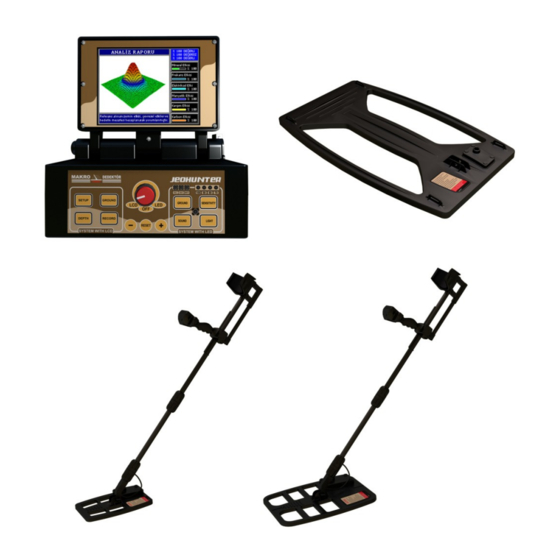
PARTS AND ACCESSORIES... - Page 7 1. Electronic System Box and Case: It is the part where the detector sockets, earphone socket joystick feed socket and battery socket are located and where measurement results are evaluated and displayed on the LCD monitor. There is a carrying apparatus for easy transport of this system.
- Page 8 3. 360x440 Detector Head: It is the system that consists of the detector head for general purposes. There are no LEDs on this system and operator follows the results on a LCD monitor located on the system box. This system can only be used in LCD mode.
- Page 9 Batteries: 14.8 V, 4 Ampere Lithium Ion rechargeable batteries. Battery Operating Voltage (Min): 12 V Battery Operating Voltage (Max): 14.8 V Battery Current: 4 A Battery Life: 4-6 hours Battery Charger: It is a device to charge 14.8 V 4 Ampere Lithium Ion batteries.
-
Page 10: System Unit And Joystick
SYSTEM UNIT and JOYSTICK... - Page 11 ELECTRONİC SYSTEM UNIT 1- SCAN: A key that enables analyzing a target when pressed passing over it. 2- ACCEPT: The key that approves the related function and enable to switch to the previous menu. 3- SETTING: The key that allows switching to the Settings Menu. 4- GROUND: The key that allows switching to Ground Setting mode in LCD system mode.
- Page 12 5- DEPTH: The key that enables the device to switch to diameter screen and carry out depth analysis. 6- RECORD: The key that enables entry to recording screen in addition to recording the report in report analysis section. 7- “ – “ : The minus key. 8- RESET: Resets all detector settings (Default Settings) in reference to recent settings whenever resetting is done.
- Page 13 JOYSTICK 1 – SCAN: The key that enable the target to be analyzed when passing over the target. 2- CAVITY and MINERAL: “CAVITY and MINERAL” LEDs glow when void and mineral is detected during exploration process. Number of glowing lights varies depending on the power of detected signal. All LEDs glow when a powerful signal is detected.
-
Page 14: Assembly And Charging The Battery
ASSEMBLY AND CHARGING THE BATTERIES... - Page 15 1. ASSEMBLY: Detector head is taken off the carrying case and telescopic extension tube is inserted, piece Nr.1 into piece Nr.2 as shown in the diagram and tighten the sleeve. The detector head is dismounted from the extension tube when packing in the carrying case.
- Page 16 DETECTOR HEAD CONNECTION Transmits the data received from detector head to the Electronic system box. The 5 pin “B” plugs shown in the above figure are connected to socket “B” on the system box. JOYSTICK CONNECTION Joystick transmits the received data to the Electronic system box. The 8 pin “A”...
- Page 17 2. CHARGING THE BATTERIES: Battery Charger State without Batteries Installed: When the charger is connected to the mains plug, the green light on the charger is lit and triggers a short alarm tone. Detection of a defective Battery: When a defective battery is connected to the charger green light on the charger blinks 5 times, a short beep tone is heard and the green light...
-
Page 18: Using With Led System
USING WITH LED SYSTEM... - Page 19 PLEASE NOTE: The LED function of the device can only be used when 210x315 detector head is mounted. Mount the 210x315 detector head as defined in the System box “assembly” section. When detector heads other than 210x315 is mounted on the device the operator is warned by audio and visual alarms.
- Page 20 Utilization of the LED Switch and Lighting Principles of the LEDs: “LED” switch is used for adjusting the level of illumination. The device is designed for day and night use. The illumination level may be adjusted to the maximum by using this switch and enable the lights to be visible even under sunlight.
- Page 21 NOTE: When the battery is depleted the three “BATTERY” lights blink and a sound alarm is triggered. NOTE: When the detector head is out of order or it is not conceived, all four “SENSITIVITY” LEDs blink and a sound alarm is triggered. Sound Button Usage and Sound Alarm Principles: “SOUND”...
- Page 22 Using the SCAN Button: This button is used to analyze the target in case the “VALUABLE” LED is on during you explore. The target that caused the “VALUABLE” LED to turn on is re scanned while pressing the “SCAN” button. If the “VALUABLE”...
-
Page 23: What Is Ground Setting And How It Is Done
WHAT IS GROUND SETTING AND HOW IT IS DONE? In our country land formation and soil composition vary in relation to regions. In some regions the composition may vary frequently (Sand, lime, red earth with dense mineral content, rocky formation, etc.). These variations in soil composition mislead the detector and cause perception as metal or void. -
Page 24: Ground Setting Phases
Ground Setting Phases To make ground setting the device is turned on in “LED” mode and “GROUND” button is pressed. 2. Make sure that there are no metals or voids in the ground where ground setting will be made. If ground setting could not be adjusted it will be repeated in a neighboring area. - Page 25 “ If “METAL and MINERAL” warning is received: Lift the detector head of the device 40 cm above ground and press (+) button a couple of times. Perform resetting immediately Reset Lower the detector head again 5-10 cm distance to the ground. ...
- Page 26 In this case lift the detector head of the device 40 cm above ground again and press “+” button a couple of times more, perform resetting. Lower the detector head again to the ground to the same distance. If the lights are on and sound alarm continues (after each operation the number of lights will decrease) continue this operation until the effect is eliminated.
- Page 27 If the ground effect on the device is eliminated by this procedure none of “Void and Mineral” lights turn on (Metal and Mineral lights should also not turn on). This means the device is suitable for exploring in that area.
- Page 28 8. If the ground settings cannot be realized by above described operations, “SENSITIVITY” level of the device should be decreased one step and above mentioned operations are repeated. NOTE: If there is difficulty in making ground settings in tough ground (having dense mineral content) and the setting could not be made successfully it is possible to carry out exploration when a single light is on “Metal and Mineral”...
-
Page 30: Performing Search With Led System
EXPLORE MODE WITH LIGHT SYSTEM... - Page 31 After the “GROUND” adjustment is made “GROUND” button is pressed and when the light in the middle goes off the device is ready for exploration. The detector head of the device is lifted 40 cm above ground and reset.
- Page 32 During exploration if a precious metal is suspected “PRECIOUS” light on the joystick turns on and warns the operator. The operator receiving this warning press the “SCAN” button on the joystick and makes a second pass over the target. After this operation if “PRECIOUS”...
-
Page 34: Using With Lcd System
USING WITH LCD MODE... - Page 35 NOTE: The LCD system function of the device can only be used when 360x440 detector head and 600x1000 detector head is installed. Install the 360x440or 600x1000 detector head to the system box as described in the “assembly” section. The device has two separate systems. One of these systems is the LED System, the other is LCD System.
- Page 36 Coil and System Error Warnings: If there is an error in the detector head or in the system “SERCHING HEAD FAULT” or “SYSTEM FAULT” warning lights blink at the bottom of the screen and a sound alarm is heard to warn the operator after the device is switched on.
- Page 37 Adjusting LIGHT Level: “SETUP” button pressed adjusting the level of light of the device in whatever mode is it in. The current adjusted light level is displayed as % on the screen. Select the “LIGHT” mode by pressing “+” and “-“ keys as described above.
- Page 38 Select the “SOUND” mode by pressing “+” and “-“ keys as described above. After this mode is selected press the “ACCEPT“ button, the sound indicator bar will turn from yellow into green. Adjust the sound level by pressing “+” and “-“ keys and press “ACCEPT” button. The green indicator bar turns back into yellow.
- Page 39 Adjustment of IRON Mode: “SETUP” button pressed switching the level of IRON mode of the device on and off in whatever mode is it in. The current IRON mode is displayed as open or closed. You may find more detailed information about the properties of this mode and how it is used in following sections.
-
Page 40: How Ground Setting Is Made
HOW IS GROUND SETTING DONE? When the device is switched on it starts with the GROUND ADJUST” mode. Ground adjustment should be done before using the device for correct results. During exploration when soil composition has changed and when ground adjustment has to be done again switch to ground mode by pressing the “GROUND”... - Page 41 5. The operator lifts the detector head “40 cm” above ground and after resetting lower the detector head “5-10 cm” parallel to the ground. 6. If there is no ground effect on the device there is no interaction on the bar that is indicated in the figure and “Ground Setting 100% Completed”...
- Page 42 After pressing “+” or “-“ buttons lift the detector head 40 cm above ground and press the “RESET” button and observe the ground effect by holding the detector head 5-10 cm above ground, if ground effect persists try to eliminate this effect by pressing “+” or “-“ buttons. If we are not able to eliminate the ground effect decrease the sensitivity level one step and repeat the above defined operation.
-
Page 44: Performing Search With Lcd System
EXPLORE MODE WITH LCD SYSTEM... - Page 45 After “GROUND“ setting is completed “ACCEPT” button is pressed and switched to Explore Mode. The detector head is lifted 40 cm above ground and the “RESET” button is pressed. Hold the detector head 5-10 cm above and parallel to the ground. You can explore by moving the detector head slowly with a right o left sweeping motion or by walking straight.
- Page 46 If the target is valuable metal, there is a raise both on the “METAL” and ”VALUABLE” that is expressed in % depending on the magnitude of the effect. The effect of metal can be monitored in the graph on top of the bars.
- Page 47 Worthless Metals Elimination Function: The device can enable to filter the worthless metals by the device and warn the operator if desired. For this operation “IRON” mode should be off. To switch off this mode press “SETUP” button when in explore or ground modes.
- Page 48 Detection of Target Depth: For detecting target depth during exploring: Press the “DEPTH” key when in explore mode after the target is detected. First the dimensions of the target should be determined depth mode. This operation is explained in detail with operator help menu.
- Page 49 Enter the “Length” value by using “+” and “-“ keys. Press the “ACCEPT” button after entering the length value. Press the “SCAN “ button after this operation and pass over the target again and release the “SCAN” button ...
- Page 50 Press the “ACCEPT” button when in the record menu. On top of the monitor there are “Erase record” “Exit” windows. Use the “+” and “-“ keys activate these windows. Press “ACCEPT” button when there is a frame around “Exit” window to exit from...
-
Page 51: Jeohunter Technical Properties
TECHNICAL PROPERTIES...
Need help?
Do you have a question about the JEOHUNTER 3D Dual System and is the answer not in the manual?
Questions and answers
Hello Dear. My Coil Is dost Not Detected Gold How To Fix
To fix the issue of the coil not being detected on the Makro 3D Dual System:
1. Ensure the 5-pin cable of the search coil is fully inserted into the socket on the system box.
2. Make sure the cable fits the finger hold correctly.
3. Tighten and fix the screw at the connector to secure the connection.
These steps help ensure proper connection between the coil and the system.
This answer is automatically generated