Table of Contents

Subscribe to Our Youtube Channel
Related Manuals for Schroeder Industries HY-TRAX

Summary of Contents for Schroeder Industries HY-TRAX
- Page 1 L-4370 Manually Controlled Fluid Sampling System Operating and Maintenance Instructions 580 West Park Road | Leetsdale, PA 15056 ph. 724.318.1100 | fax 724.318.1200 www.schroederindustries.com An ISO 9001:2015 Certified Company...
- Page 2 L-4370 | Created 4.2015 Rev. 5.2017...
-
Page 3: Table Of Contents
- TABLE OF CONTENTS- HY-TRAX ® 1. Features and Precautions ...............................6 1.1 Features ..................................6 2. Warnings, Cautions, and Notes .............................6 2.1 Technical Assistance ..............................8 2.2 Obligations and Liabilty ...............................9 2.3 Acronym List ................................9 2.4 Components ................................10 3. Specifications ................................11 4. Connecting Your System ..............................12 5. - Page 4 14.1. Function of the Keys ..............................35 14.2. Measured variables on the display .........................36 14.3. ISO (Cleanliness class) ............................36 14.4. SAE (Cleanliness class) ............................36 14.5. NAS (Cleanliness Class - only TCM 13xx) ......................36 15. Service variables on the display ..........................36 15.1. Flow (flow rate) ...............................36 15.2.
- Page 5 22.2.4. HDA.ISO – Analog signal ISO to HDA 5500 ....................61 22.2.5 HDA.ISO Signal 1/2/3/4 ..........................62 22.2.6. HDA.ISO signal 5 (status) ..........................63 22.3.ISO code signal acc. to ISO 4406:1987 (TCM 13xx only) ...................64 22.3.1. ISO 2 / ISO 5 / ISO 15 ..........................64 22.3.2.
-
Page 6: Features And Precautions
■ Provides Local Visibility to the Fluid Condition of Critical Systems. ■ I ntegrated micro VSD, (Variable Speed Drive), pump/motor provides optimal flow for accurate sensor readings in variable conditions. ■ T he HY-TRAX Manually Controlled Fluid Sampling System allows a user to retrieve ISO cleanliness levels from a ® reservoir tank or a low-pressure line (<50 psi max). ■ The compact design allows for installations with tight space constraints. - Page 7 User Manual HY-TRAX L-4370 ® Operate Only If Qualified Do not operate this machine unless you have read the operator’s manual carefully and you have been qualified by supervised training and instruction. Familiarize yourself with the job site and your surroundings before operating. Inspect Machine Inspect the equipment carefully before each use. Keep all parts in good condition and properly installed. Fix damage and replace worn or broken parts immediately.
-
Page 8: Technical Assistance
L-4370 HY-TRAX User Manual ® Illuminate Work Area Safely Illuminate your work area adequately but safely. Use a portable safety light for working inside or under the machine. Make sure the bulb is enclosed by a wire cage. The hot filament of an accidentally broken bulb can ignite spilled fuel or oil. Work In Clean Area Before starting a job: ■... -
Page 9: Obligations And Liabilty
Edition Date Document Language While every precaution has been taken to ensure accuracy and completeness in this literature, Schroeder Industries assumes no responsibility, and disclaims all liability for damages resulting from use of this information or for any errors or omissions. -
Page 10: Components
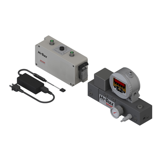
L-4370 HY-TRAX User Manual ® 2.4 Components Component Definitions Manual Controller 115VAC x 24VDC Variable Speed TestMate Contamination ® Power Supply/Converter Pump/Motor Monitor (TCM) Manifold Block 0-160PSI Pressure Gauge Flow Control Valve Schroeder Industries... -
Page 11: Specifications
User Manual HY-TRAX L-4370 ® 3. Specifications Design Parameters Measuring Range: Display ISO ranges between 25/24/23 and 9/8/7 Calibration within the range ISO 13/11/10 to 23/21/18 Contamination Output Code: Standard: ISO 4406:1999 or SAE AS 4059(D) Optional: ISO4406:1987; NAS 1638 and ISO 4406:1999 Self Diagnosis: Continuously with error indication via status LED Fluid Inlet/Outlet: 50 psi (3.4 bar) max... -
Page 12: Connecting Your System
Connect 5 pin supplied cable to Motor connection and control box ‘Motor/Pump Power’ as shown on drawing 7628266 (see page 14). WARNING The HY-TRAX manual controller requires 24 DC power in order to operate. The optional AC/DC converter ® (SAP# 7600601) can be used. Or, see page 21 for wiring the supplied 24 VDC connector. - Page 13 User Manual HY-TRAX L-4370 ® Schroder Industries...
- Page 14 L-4370 HY-TRAX User Manual ® Schroeder Industries...
-
Page 15: Operating Instructions
User Manual HY-TRAX L-4370 ® 5. Operating Instructions STEP ONE With the unit powered on, the TCM display should be illuminated and power will be supplied to the pump/motor. The TCM will show ISO cleanliness readings 90 seconds after powering up. - Page 16 L-4370 HY-TRAX User Manual ® Schroeder Industries...
-
Page 17: Parts List
THESE DRAWINGS, SPECIFICATIONS, AND THE IDEAS CONTAINED HEREIN ARE THE EXCLUSIVE PROPERTY 7633259 OF SCHROEDER INDUSTRIES AND ARE CONFIDENTIAL. HYTRAX MANUALLY CONTROLLED FLUID SAMPLING SYSTEM THESE DOCUMENT(S) SHALL NOT BE COPIED OR REPRODUCED IN PART OR IN FULL AS A BASIS OR DESIGN,... - Page 18 L-4370 HY-TRAX User Manual ® Schroeder Industries...
-
Page 19: Maintenance
User Manual HY-TRAX L-4370 ® 7. Maintenance ■ Check fittings periodically to ensure they are tight. ■ Check suction and discharge hoses for leaks, cracks…etc. ■ For TCM maintenance, refer to section 9 of this manual. ■ Inspect unit periodically for leaks. Internal leaks will be caused by faulty O-rings. Refer to the parts list shown in Section 6 for O-ring part numbers and contact your sales representative. - Page 20 L-4370 HY-TRAX User Manual ® Schroeder Industries...
- Page 21 User Manual HY-TRAX L-4370 ® Schroder Industries...
-
Page 22: Vdc Connection Instructions
L-4370 HY-TRAX User Manual ® ASSEMBLY INSTRUCTION NC * FXX & NC * MXX XLR Cable Connector Slide the boot onto the cable. Prepare cable as shown. Insert the positive wire on terminal #1 and the negative wire on terminal #2 and solder them. -
Page 23: Testmate ® Contamination Monitor | Tcm
L-4370 TestMate Contamination Monitor | TCM ® Operating and Maintenance Instructions 580 West Park Road | Leetsdale, PA 15056 ph. 724.318.1100 | fax 724.318.1200 www.schroederindustries.com Schroeder Industries An ISO 9001:2015 Certified Company... -
Page 24: Qualifications Of Personnel/Target Group
Rinse the TCM completely with Cleanoil before putting it into storage. The solvents and flushing oils used must be handled and disposed of correctly. 2.1. Storage conditions Storage temperature: -40 °C … 80 °C / -40 °F … + 176 °F Relative humidity: maximum 95%, non-condensing 3. Decoding the model code label For product identification details see the Model code label. This is located on the back of the unit and contains the exact product description and the serial number. Schroeder Industries... -
Page 25: Checking The Scope Of Delivery
User Manual L-4370 Description Model Model Code Part no. Serial no. Date Year/week of production and hardware index Max. INLET press Maximum operating pressure 4. Checking the scope of delivery The TestMate Contamination Sensor TCM comes packed and factory-assembled, ready for operation. Before starting up ®... -
Page 26: Tcm Features
All models feature an analog electric output and an RS485 interface for outputting the measured cleanliness class. In addition, all TCM’s have a switching output. 6. TCM Restrictions on use TCM1x1x dimensions (without display) TCM1x1x dimensions (without display) All dimensions in mm Schroeder Industries... -
Page 27: Hydraulic Connection Types
User Manual L-4370 8.1. Pipe or hose connection (type TCM) Hydraulic connection is done via ports A and B. Connection thread G1/4 according to ISO 228. Make sure that the flow runs through the sensor from bottom (A) to top (B). 8.2. Flange connection type (Type TCM) Hydraulic connection is done via ports C and D. Two O-rings are used to form a seal between the TCM and a flange, connecting plate or manifold mount. Four M6 threads are prepared for fixing the TCM. Ports A and B are sealed off with screw plugs [1]. Sealing with the manifold block or mounting plate is done via two O-rings [2] (4.48 x 1.78 FPM, see Chapter “Spare Parts +... -
Page 28: Display Rotatable/Adjustable As Needed
Pipe/hose connection The TCM is connected to the hydraulic system via ports A and B using a pipe or hose. Flange connection The TCM is screwed to a flange, connecting plate, manifold mount or control block, with flow through the unit via ports C and D on the bottom. Ports A and B exist but are sealed with a screw plug Determine the operating pressure of the hydraulic system and see whether it is within the permissible flow range for the TCM inlet Schroeder Industries... -
Page 29: Selecting The Measurement Point
User Manual L-4370 NOTE Excessive operating pressure The TestMate Contamination Sensor will be destroyed: Note the maximum operating pressure of 350 bar / 5075 psi. ® 11.1. Selecting the measurement point In order to obtain cleanliness values that are continuous and coherent in real time, select a suitable measuring point ac- cording to the following guidelines: WRONG WRONG... -
Page 30: Hydraulic Connection Of The Tcm
Contamination Sensor. (e.g. CM-S). 5. Connect the other end of the measurement line to the measurement point on the hydraulic system. WARNING Oil begins to flow as soon as the TestMate Contamination Sensor is connected with the pressure line. ® 6. The hydraulic connection is complete. Schroeder Industries... -
Page 31: Electrical Connection Of The Tcm
User Manual L-4370 12. Electrical Connection of the TCM 12.1. Pin Assignment Assignment Supply voltage 9 ... 36 V DC Analog output + (active) GND supply voltage GND ANALOG / SWITCH OUTPUTS HSI (SCHROEDER Sensor Interface) RS485 + RS485 - Switching output (passive, n.c.) The analog output is an active source of 4 ... -
Page 32: Connection Cable - Assignment / Color Coding
Brown Analog output + (active) Green GND supply voltage Yellow GND ANALOG / SWITCH OUTPUTS Gray HSI (SCHROEDER Sensor Interface) Pink RS485 + Blue RS485 - Switching output (passive, n.c.) Housing screen 12.3. Connecting cable ends - Examples Schroeder Industries... -
Page 33: Setting The Measuring Mode
User Manual L-4370 Circuit diagram: with one power supply. (e.g. 24 V DC). To prevent a ground loop, connect the shield of the connector cable if and only if the TCM is not grounded or not sufficiently connected to the PE conductor. 13. Setting the measuring mode Once the sensor is switched on or supplied with power, it automatically runs in the measuring mode that has been set. -
Page 34: Mode M4: Filter To Continuously Monitor Cleanliness Class
This is followed by a countdown: WAIT99 … WAIT0. The duration of the countdown corresponds to the set measurement time MTIME. This means that the countdown runs from 99 ... 0 within the set measurement time (factory setting = 60 sec). Schroeder Industries... -
Page 35: Function Of The Keys
User Manual L-4370 14.1. Function of the Keys Item Description Status Status Display Display 6-figure display with 17 segments each Measured Display of respective measured variable, Variable e.g: ISO / SAE / NAS Additional Display of respective service variable, Variable e.g.: Flow / Out / Drive / Temp Switch Point 1 Indicates the status of the switching output. -
Page 36: Measured Variables On The Display
15. Service variables on the display The service variables inform you about the current status in the TestMate® Contamination Sensor . The service variables are not calibrated. They represent an approximate value for installing the sensor in the hydraulic system. Flow (Flow Rate) Schroeder Industries... -
Page 37: Out (Analog Output)
User Manual L-4370 16. Activate / deactivate keypad lock. Activate or deactivate the keypad lock by pressing both keys simultaneously to prevent further input. The display switches to the preset display after 1 second. When the supply voltage to the TCM is disconnected, the activated keypad lock “LOCK” is unlocked and reset to “UNLOCK”. -
Page 38: Display Freeze
If the memory exceeds 20 display values, the oldest entry will be overwritten. 17.1 Activate display FREEZE To activate or deactivate the history memory FREEZE, press both keys simultaneously. The FREEZE function starts with the display of the most recent measured value. Schroeder Industries... -
Page 39: Deactivate Display Freeze
User Manual L-4370 17.2. Deactivate display FREEZE If display FREEZE is set to MANUAL in the PowerUp menu: Press the following two keys simultaneously to return to the current display If the display FREEZE is set to TIMEOUT in the PowerUp menu: You are returned automatically to the current display after 10 times the value for MTIME, or manually by pressing both arrow keys simultaneously. - Page 40 L-4370 User Manual Schroeder Industries...
-
Page 41: Measuring Menu (Tcm12Xx)
User Manual L-4370 18.2 Measuring Menu (TCM12xx) During measurement operation, you can perform the following settings: Schroder Industries... -
Page 42: Dsplay - Display After Sensor Is Switched On
Here you can adjust the behavior of the switching output. The measurement mode “M1 / M2 / M3 / M4 / SINGLE” is cop- ied from the setting in the PowerUp menu and can no longer be selected here. Schroeder Industries... - Page 43 User Manual L-4370 Schroder Industries...
-
Page 44: Ana.out - Set Output Signal At Analog Output
L-4370 User Manual ANA.OUT - Set output signal at analog output The measured variable set here is output at the analog output Schroeder Industries... -
Page 45: Overview Of Menu Structure
User Manual L-4370 19. Overview of menu structure 19.1 Menu TCM 12xx (ISO 4406:1999 and SAE) Power Up Menu Schroder Industries... - Page 46 L-4370 User Manual Measuring Menu Schroeder Industries...
-
Page 47: Menu Tcm 13Xx (Iso 4406:1987 And Nas / Iso4406:1999 And Sae 4059 D)
User Manual L-4370 19. Overview of menu structure 19.1 Menu TCM 12xx (ISO 4406:1999 and SAE) Power Up Menu Schroder Industries... -
Page 48: Using Switching Output
20.4. Mode M4: Filter to continuously monitor cleanliness class Purpose: Establish continuous monitoring of cleanliness class between min/max limit values Function: If min/max limit values are pre-programmed, the TCM switches the filter unit on/off to keep cleanliness within the limit value range Load the switching output with a maximum of 2 A and 30 V DC. Schroeder Industries... -
Page 49: Mode "Single" Measurement
User Manual L-4370 20.5. Mode “SINGLE” measurement Purpose: Perform a single measurement and “stop” the result. Function: Single measurement of solid contamination without switching functions Switching function only for “Device ready”. 21. Setting limit values The voltage supply to the TCM makes the switching output (SP1) conductive. This condition is maintained for the initial measurement duration (WAIT period). - Page 50 L-4370 User Manual Schroeder Industries...
-
Page 51: Reading The Analog Output
User Manual L-4370 22. Reading the analog output Depending on TCM model, the analog output is available as a 4 ... 20 mA or 2 ... 10 V signal. You can recognize the type of analog output from the model code of the sensor. TCM Model code Analogue output TCM 1 x x x - A – x – x – x – x /-xxx 4 …... -
Page 52: Sae A-D
For example: a readout of SAE 10.7 is, according to SAE 4059 (D), a class SAE 11. 22.1.2 SAE Class A / B / C / D slices: The SAE class A/B/C/D signal consists of 4 measured values transmitted with the following time-coded time Schroeder Industries... -
Page 53: Sae A / Sae B / Sae C / Sae D
User Manual L-4370 22.1.3 SAE A / SAE B / SAE C / SAE D The SAE X signal consists of a measured value (SAE A / SAE B / SAE C / or SAE D) which is permanently transmitted as described in the following. -
Page 54: Sae + T
User Manual mTIME = Duration of the measurement as set in the PowerUp menu, see page 30. 22.1.4. SAE + T The SAE+T signal consists of 5 measured values which are transmitted time-coded with the following time slices: Schroeder Industries... - Page 55 User Manual L-4370 Schroder Industries...
-
Page 56: Hda.sae - Analog Signal Sae To The Hda 5500
Current / Voltage for signal Pause 4 mA / 2 V Signal 4 SAE D Current / Voltage for signal Pause 4 mA / 2 V Signal 5 Status Current / Voltage for signal Pause 4 mA / 2 V Schroeder Industries... -
Page 57: Hda.sae Signal 1/2/3/4
User Manual L-4370 22.1.6. HDA.SAE Signal 1/2/3/4 The current or voltage range is dependent on the contamination class according to SAE=0.0 – 14.0 (resolution 0.1 class). Current I SAE class / Error Voltage U I < 4.00 mA Cable break U< 2.00 V I = 4.00 mA SAE 0 U = 2.00V …... -
Page 58: Iso Code Acc. To Iso 4406:1999
All values are sequentially time-coded before output. ISO+T ■ All values are sequentially time-coded before output. ■ HDA.ISO All values are sequentially time-coded before output. This signal is planned for the HDA 5500, but it can be used also in other applications. Schroeder Industries... -
Page 59: Iso 4 / Iso 6 / Iso 14
User Manual L-4370 The current 4.8 … 19.2 mA or voltage 2.4 … 9.6 V of the output signal depends on the ISO contamination class 0.0 … 24.28 (resolution 1 class) or on an error as described below: Current I ISO code / error Voltage U I < 4.0 mA... -
Page 60: Iso Code, 3-Digit
L-4370 User Manual 22.2.2. ISO code, 3-digit The ISO code signal consists of 3 measured values (>4µm(c) / >6µm(c) / >14µm(c)) which are transmitted time-coded. Schroeder Industries... -
Page 61: Iso + T
User Manual L-4370 22.2.3. ISO + T The ISO+T signal consists of 4 measured values which are transmitted time-coded with the following time slices: Time Signal Size Signal duration Current (I) / Voltage (U) per pulse in ms 1 Identifier >4µm(c) 300 High / Low 2 Measured value >4µm(c) 3000 Current/Voltage for measured value 3 Identifier >6µm(c) -
Page 62: Hda.iso Signal 1/2/3/4
The ISO contamination class can be calculated for a given current I or voltage U as follows: ISO code = (I - 4 mA) x (24.28 / 16 mA) ISO code = (U - 2 V) x (24.28 / 8 V) Schroeder Industries... -
Page 63: Hda.iso Signal 5 (Status)
User Manual L-4370 22.2.6. HDA.ISO signal 5 (status) The current or voltage of the output signal (5) is dependent on the status of the TCM as shown in the table below: Current I Status Voltage U I = 5.0 mA The TCM is functioning correctly. -
Page 64: Iso Code Signal Acc. To Iso 4406:1987 (Tcm 13Xx Only)
ISO code = (I - 4.8 mA) x (24.28 / 14.4 mA) ISO code = (U - 2.4 V) x (24.28 / 7.2 V) 22.3.1. ISO 2 / ISO 5 / ISO 15 The ISO X signal consists of a measured value (> 2 µm or > 5 µm or > 15 µm) which is permanently transmitted, as de- scribed in the following. Schroeder Industries... - Page 65 User Manual L-4370 mTIME = Duration of the measurement as set in the PowerUp menu. Schroder Industries...
-
Page 66: Iso Code, 3-Digit
L-4370 User Manual 22.3.2. ISO code, 3-digit The ISO code signal consists of 3 measured values (>2 µm / >5 µm / >15 µm) which are transmitted time-coded as shown below. Schroeder Industries... -
Page 67: Iso + T
User Manual L-4370 22.3.3. ISO + T The ISO+T signal consists of 4 measured values which are transmitted time-coded with the following time slices: Schroder Industries... -
Page 68: Hda.iso - Analog Signal Iso To Hda 5500
22.3.4. HDA.ISO – Analog signal ISO to HDA 5500 The HDA.ISO signal consists of 4 measured values (ISO 4 / ISO 6 / ISO 14 / ISO 21 / Status) which are output sequentially. Synchronization with the downstream control unit is a prerequisite. The signal output is as follows: Schroeder Industries... -
Page 69: Hda.iso Signal 1/2/3/4
User Manual L-4370 22.3.5 HDA.ISO Signal 1/2/3/4 The current 4 … 20 mA or voltage 2 … 10 V of the output signal depends on the ISO contamination class 0.0 … 24.28 (resolution 1 class) as described below: Current I ISO Code Voltage U I < 4.00 mA... -
Page 70: Nas 1638 - National Aerospace Standard (Only Tcm 13Xx)
U = 2.4 V + NAS class x (9.6 V - 2.4 V) / 14 The current I or voltage U can be calculated for a given NAS contamination class as follows: NAS class = (I - 4.8 mA) x (14/14.4 mA) NAS class = (U – 2.4 V) x (14/7.2 V) Schroeder Industries... -
Page 71: Nas Maximum
User Manual L-4370 22.4.1 NAS maximum The NAsMAX value designates the largest of the 4 NAS classes. NAS class 2 µm 5 µm 15 µm 25 µm Particle size 2-5 µm 5-15 µm 15 µm > 25 µm The signal is updated after the measuring period has elapsed (the measuring period is set in the PowerUp menu, factory setting = 60 s). -
Page 72: Nas Classes (2 / 5 / 15 / 25)
L-4370 User Manual 22.4.2 NAS classes (2 / 5 / 15 / 25) NAS class signals 2 / 5 / 15 / 25 consist of 4 measured values transmitted with the following time-coded time slices: Schroeder Industries... -
Page 73: Nas 2 / Nas 5 / Nas 15 / Nas 25
User Manual L-4370 22.4.3 NAS 2 / NAS 5 / NAS 15 / NAS 25 The NAS X signal consists of a measured value (NAS 2 / NAS 5 / NAS 15 / NAS 25) which is permanently transmitted, as described below. -
Page 74: Nas + T
L-4370 User Manual 22.4.4. NAS + T The NAS+T signal consists of 5 measured values which are transmitted time-coded with the following time slices: Schroeder Industries... -
Page 75: Hda.nas - Analog Signal Nas To Hda 5500
User Manual L-4370 22.4.5 HDA.NAS – Analog Signal NAS to HDA 5500 The HDA.NAS signal consists of 4 measured values (Start / NAS 2 / NAS 5 / NAS 15 / NAS 25 / Status) which are output sequentially. Synchronization with the downstream control unit is a prerequisite. The signal output is as follows: 22.4.6. -
Page 76: Hda.nas Signal 5 (Status)
If the status signal is 8.0 mA or 4.0 V, signals 1 to 4 are output as follows. Signal Current I Voltage U NAS class 4.0 mA 2.0 V 4.0 mA 2.0 V 4.0 mA 2.0 V 4.0 mA 2.0 V Schroeder Industries... -
Page 77: Fluid Temperature Temp
User Manual L-4370 22.5Fluid temperature TEMP The current range 4.8 … 19.2 mA or voltage range 2.4 … 9.6 V is dependent on the fluid temperature of -25°C … 100°C (resolution: 1°C) or -13°F … 212°F (resolution: 1°F) as shown in the table below. Current I Temperature / Error Voltage U I < 4.00 mA Cable break U < 2.00 V 4.0 mA < I < 4.1 mA Device error / The TCM is not ready. 2.00 V < U < 2.05 V 4.1 mA < I < 4.3 mA Not defined 2.05 V < U < 2.15 V 4.3 mA < I < 4.5 mA Flow error (The flow rate is too low.) 2.15 V < U < 2.25 V 4.5 mA < I < 4.8 mA Not defined 2.25 V < U < 2.40 V... - Page 78 L-4370 User Manual Schroeder Industries...
- Page 79 User Manual L-4370 Schroder Industries...
-
Page 80: Error
L-4370 User Manual 23.2. Error Schroeder Industries... -
Page 81: Exceptions Errors
User Manual L-4370 23.3 Exceptional Error Schroder Industries... -
Page 82: Analog Output Error Signals
(U). Please refer to chapter “Error status” for the respective values for the current strength or voltage of the output signal during an error status). The time coding is preserved. Example: “CHECK” error for the SAE output signal. Schroeder Industries... -
Page 83: Analog Signal For Hda 5500
User Manual L-4370 23.5. Analog signal for HDA 5500 HDA Status Signal 5 Table The current or voltage of the analog signal (5) is dependent on the status of the TCM as shown in the table below: Current I Status Voltage U I = 5.0 mA The TCM is functioning correctly. - Page 84 If the status signal is 6.0 / 7.0 / 9.0 mA or 3.0 / 3.5 / 4.5 V, signals 1 to 4 are output with 20 mA or 10 V. Example: If the status signal is 8.0 mA or 4.0 V, signals 1 to 4 are output as follows. Signal Schroeder Industries...
-
Page 85: Connecting Tcmi-D-5 (Condition Sensor Interface)
User Manual L-4370 24. Connecting TCMI-D-5 (Condition Sensor Interface) The TCMI-D-5 makes it possible to operate the TCM using a PC: ■ Setting parameters and limit values. ■ Reading out measurement data online. 24.1. TCMI-D-5 Connection overview Connect the TCMI-D-5 to the TCM according to the following connection diagram Schroder Industries... -
Page 86: Connecting The Tcm To An Rs485 Bus
The number of TCMs per RS485 bus is limited to 26. Use letters A to Z to address the HECOM bus address. The length of the bus line and the size of the terminating resistor depend on the quality of cable used. Connect several TCM’s using the RS485 interfaces according to the following illustration: Item Description Part no.: Converter RS232 <-> RS485 6013281 Converter USB <-> RS485 6042337 Connection cable RS232, 9-pole 2.2 Connection cable USB [A] <-> USB [B] Recommended cable twisted pair Terminator ~ 120 Ω Schroeder Industries... -
Page 87: Communicating With The Tcm Via The Rs485 Bus
User Manual L-4370 26. Communicating with the TCM via the RS485 bus To communicate with the TCM, start a terminal program (e,g, Hyperterminal) on the PC. Use the following settings to communicate via the COM interface: Bits per second 9600 Baud Data bits Parity None... - Page 88 130,000,000 4,000 8,000 130,000,000 250,000,000 8,000 16,000 Note: increasing the measurement reference by 1 causes the particle count to double. Example: ISO class 18 / 15 / 11 means: Cleanliness class Particle count / ml Size ranges 1,300 – 2,500 > 4 µm(c) 160 – 320 > 6 µm(c) 10 – 20 > 14 µm(c) Schroeder Industries...
-
Page 89: Overview Of Modifications - Iso4406:1987 <-> Iso4406:1999
User Manual L-4370 30.3 Overview of modifications - ISO4406:1987 <-> ISO4406:1999 “old” ISO 4406:1987 “new” ISO 4406:1999 Size Ranges > 5 µm > 4 µm(c) > 15 µm > 6 µm(c) > 14 µm(c) Dimension Longest dimension of a Diameter of the determined particle area-equivalent circle ISO 11171:1999 Test dust ACFTD dust 1-10 µm ultra fine ISO 12103-1A1 fraction... -
Page 90: Cleanliness Class - Sae As 4059
Max. particles / 100 ml Size B ( > 5 µm / > 6 µm(c) ) 38,900 Size C ( >15 µm / >14 µm(c) ) 3460 Size D ( >25 µm / > 21 µm(c) ) 30.6.3. Specifying highest measured cleanliness class Example: Cleanliness class according to AS 4059= 6 B – F The 6 B – F specification requires a particle count in size ranges B – F. The respective particle concentration of cleanliness class 6 may not be exceeded in any of these ranges. Schroeder Industries... -
Page 91: Cleanliness Class - Nas 1638
User Manual L-4370 31. Cleanliness Class - NAS 1638 Like ISO 4406, NAS 1638 describes particle concentrations in liquids. The analysis methods can be applied in the same manner as ISO 4406:1987. In contrast to ISO 4406, certain particle ranges are counted in NAS 1638 and attributed to measurement references. The following table shows the cleanliness classes in relation to the particle concentration determined: Maximum particle count / 100 ml 2..5 µm... -
Page 92: Measuring Menu
L-4370 User Manual 32.1 Measuring Menu 33. Specifications Schroeder Industries... - Page 93 User Manual L-4370 Schroder Industries...
-
Page 94: Recalibration
TCM device is disconnected from the power (MODE M1, M2, M4) or until the programmed target purity (MODE M3) has been reached. This series of single measurements is referred to as a measurement for convenience reasons. Schroeder Industries... - Page 95 User Manual L-4370 Schroder Industries...
Need help?
Do you have a question about the HY-TRAX and is the answer not in the manual?
Questions and answers