Advertisement
Quick Links
Advertisement

Subscribe to Our Youtube Channel
Related Manuals for Schroeder Industries TestMate Series

Summary of Contents for Schroeder Industries TestMate Series
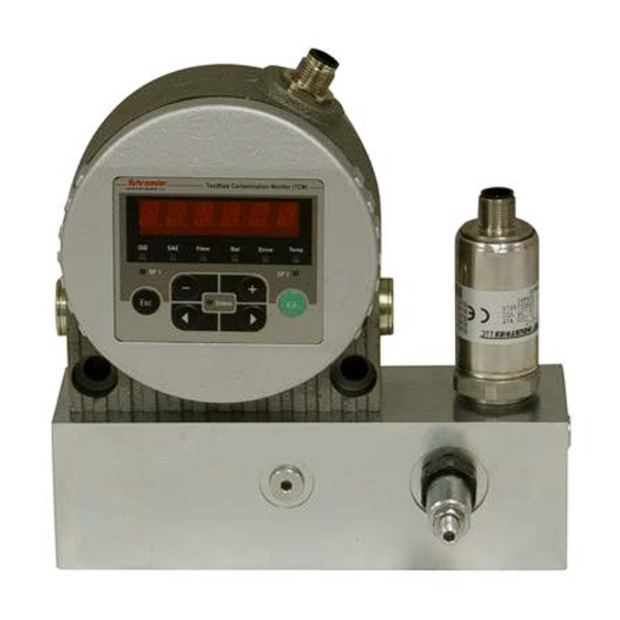
- Page 1 L-2861 ® TestMate Contamination Monitor Operating and Maintenance Instructions...
- Page 2 L-2861 | Updated 5.2016 Rev. 8.2017...
- Page 3 Installation and Operation For the TCM Block, high pressure is defined by any application with pressure in excess of 150 psi and less than the max allowable working pressure of 3,500 psi. Proper installation requires inlet flow through one of the two High Pressure SAE 4 thread inlets and return flow through one of the two SAE 4 thread outlets. The flow through the TCM Contamination Sensor is controlled by adjusting the flow control valve to achieve a minimum differential pressure of 40 psi (e.g. for a range of 500-1,000 SUS). Two gauges can be attached to the SAE 4 ports, allowing the operator to see the pressure at the inlet and outlet. While the manifold block is designed for use with low pressure/flow situations, an optional needle valve can be placed immediately following the sensor manifold, especially when influence of air in the fluid is a problem (ISO readings with equal numbers). To achieve ideal operating conditions, the TCM unit should be installed following the factory recommended procedure outlined below and noted in the TCM User Manual: 1. Install TCM in a vertical position, either the in-line version or the Block mounted version 2. Direction of flow: from IN (bottom) to OUT (top) 3. Select hydraulic hose - Minimess DN2 (2mm ID) at IN, max. 630 mm - Minimess DN4 (4mm ID) at IN (when DN2 produces an overly large pressure loss) Schroeder Industries...
- Page 4 The functionality and points of interest are shown on the above hydraulic schematic of the TCM Block. These points are the following starting from the left of the schematic: ■ H igh Pressure SAE 4 thread inlet port with Test Point attached at a single location on Block “A” ■ SAE 4 thread inlet port ■ A djustable flow control valve “B”, to regulate pressure at the inlet ■ TCM inlet ■ TCM outlet ■ Preset Orifice “C”, located within the unit ■ TWS-C/ D port (plugged if not used) ■ SAE 4 thread outlet port ■ SAE 4 thread outlet port with Test Point attached Schroeder Industries...
- Page 5 Note: If no ports are recognized, close the FluMoS application and repeat steps 4 through 8. 9. Click ”Start search”. 10. Once the particle counter is successfully discovered and connected to your computer, the measurement screen will appear as seen below. Schroeder Industries...
- Page 6 Mode M4: Filter to continuously monitor cleanliness class ..........23 Mode "SINGLE" measurement ..................24 Operating the TCM1x2x using the keypad ................ 24 Function of the Keys ......................25 Measured variables on the display ..................25 ISO (Cleanliness class) ....................26 Schroeder Industries...
- Page 7 ISO 4 / ISO 6 / ISO 14 ....................52 ISO code, 3-digit......................53 ISO + T ........................... 54 HDA.ISO – Analog signal ISO to HDA 5500 ..............55 HDA.ISO Signal 1/2/3/4 ....................56 HDA.ISO signal 5 (status) ....................56 Schroeder Industries...
- Page 8 Specifying a cleanliness code for each particle size ............83 Specifying highest measured cleanliness class ............. 84 Cleanliness Class - NAS 1638 ................... 84 Checking/resetting default settings ................... 85 PowerUp menu ........................85 Measuring menu......................... 85 Specifications ........................85 Schroeder Industries...
-
Page 9: Safety Information
Danger due to electrical voltage / current Danger due to operating pressure Signal words and their meaning in the safety information and instructions DANGER DANGER indicates a hazard with a high risk and which will lead to death or serious injury if Schroeder Industries... - Page 10 Only use the sensor for the application described in the following. ® The TestMate Contamination Sensor module serves to continuously monitor particulate contamination in hydraulic and lubrication systems. Proper or designated use of the product extends to the following: • observing all instructions contained in the instruction manual. Schroeder Industries...
Need help?
Do you have a question about the TestMate Series and is the answer not in the manual?
Questions and answers