Table of Contents
Advertisement
G
E
LECTRIC
U
NIVERSAL
I
NSTALLATION
S
P
P
L
......................................................
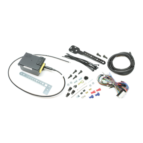
ARTS
IST
S
S
...................................................
....................................................... 23
O
I
C
LOBAL
C
RUISE
A
& O
CONTENTS
.........................................
.................................................
................................................
.........................................
..............................................
............................................. 20
................................... 24
RUISE
C
ONTROL
PPLICATION
'
M
WNER
S
Form #4565, Rev. D, 05-14-02
ANUAL
2
4
5
6
7
8
9
Advertisement
Table of Contents

Subscribe to Our Youtube Channel
Related Manuals for Rostra GlobalCruise

Summary of Contents for Rostra GlobalCruise
-
Page 1: Table Of Contents
LOBAL RUISE LECTRIC RUISE ONTROL NIVERSAL PPLICATION & O ’ NSTALLATION WNER ANUAL CONTENTS ......... AFETY ROCEDURES ..........ELPFUL INTS ............ARTS ..........ARTS IAGRAM ......... UPPLEMENTAL ARTS ..........WITCH ETTINGS ........... NSTALLATION ..........20 ROUBLESHOOTING ............23 ARRANTY ........24 PERATING NSTRUCTIONS Form #4565, Rev. -
Page 2: Afety Rocedures
GlobalCruise WARNING Failure to follow the instruction manual could not only cause the GlobalCruise to work improperly, but could cause the throttle to hang up, possibly causing damage to your vehicle and injury and/or death to you and your passengers. - Page 3 Nevertheless, there are residual risks! Throttle Adaptor GlobalCruise Target Group and Qualified Installation GlobalCruise Modifications to the product GlobalCruise Inform the user WARNING GlobalCruise GlobalCruise Page 3...
-
Page 4: Helpful Hints
ELPFUL INTS 1. BEFORE STARTING INSTALLATION: GlobalCruise 2. MATING CONNECTORS: Figure A CAUTION Figure A Figure B 3. AIRBAG AND ANTI-THEFT RADIO: Figure B 4. REMOVAL OF NEGATIVE BATTERY CABLE: GlobalCruise Figure C Figure C 5. ACCESSORY POWER: Figure D. - Page 5 SERVICE ITEM PART # DESCRIPTION 58”) (102 (190 HREADED LAMP (#10-32) MM X (16-22 AWG) (16-18 AWG) (#10-32 (Kit# 250-4206) LUTCH ISENGAGEMENT WITCH Dark Blue TACH GlobalCruise (See Service Part Numbers Service Parts above). Additional Hardware Page 7 Page 5...
-
Page 6: Parts Diagram
ARTS IAGRAM G3 G4 G5 G11 G12 WARNING GlobalCruise Page 6... -
Page 7: Supplemental Parts
UPPLEMENTAL ARTS GlobalCruise ROSTRA SERVICE ITEM PART # DESCRIPTION (250-4291 and 250-4292) HROTTLE OUPLER HROTTLE OUPLER LASTOMER ETAINER (250-2262) EDAL RACKET SSEMBLY EDAL RACKET M5-.8 12 B M5 N (2) P OCKING LAIN ASHERS Page 7... -
Page 8: Witch Ettings
ODULE The twelve (12) programming switches are twelve (12) located under the Black Rubber Grommet on top of the C RUISE ODULE GlobalCruise Figure 1 NOTE 1: VSS (Gray) TACH (Dark (If the Gray wire is Blue) not used, an auxiliary road speed source must be used.) - Page 9 ODULE OLTS ODULE RACKET Figure 2 NOTE DO NOT OVERTIGHTEN! DAMAGE TO THE CRUISE MODULE WILL OCCUR IF THE BOLTS ARE OVERTIGHTENED. RUISE ODULE two (2) HREADING OLTS RUISE (See Page 7) ODULE GlobalCruise Figure 3 WARNING GlobalCruise Page 9...
-
Page 10: Installation
NSTALLATION II. MEASURING THROTTLE CABLE TRAVEL THIS IS A VERY IMPORTANT STEP. FAILURE TO DETERMINE THROTTLE CABLE TRAVEL COULD CAUSE DAMAGE TO YOUR VEHICLE AND/OR GlobalCruise. MEASURE ONLY WITH THE ENGINE OFF. 41mm (1-5/8”). RUISE ABLE Figure 4 “A” (Idle) “B”... - Page 11 NSTALLATION III. ATTACHING CRUISE CABLE TO THROTTLE five (5) T-BAR ADAPTER ABLE DAPTOR Page 7) D. Ford™ Figure 8 E. General Motors™ Chrysler™ HREE ONNECTOR ABLE OPEN ABLE ABLE Figure 9 ABLE RUISE Figure 9 ABLE HAIN ONNECTOR ONNECTOR OVER ABLE HAIN ONNECTOR...
- Page 12 HAIN ONNECTOR ONNECTOR OVER HAIN . Figure 12 ONNECTOR LAMP LAMP HAIN RUISE ABLE HAIN ONNECTOR ONNECTOR OVER Figure 12 HAIN HAIN YELET ONNECTOR ONNECTOR OVER M5 B LAMP YELET ONNECTOR OCKNUT Figure 13 Figure 13 WARNING GlobalCruise Page 12...
- Page 13 ONNECTOR OVER M5 B Figure 14 LAMP YELET ONNECTOR OCKNUT Figure 14 4. Figure 15 Ford™ LAMP Figure 15 E. General Motors™ Chrysler™ HREE ONNECTOR General Motors™ Chrysler™ HREE ONNECTOR Figure 16 RUISE ABLE Figure 16 WARNING GlobalCruise Page 13...
- Page 14 HAIN ONNECTOR LIP W ABLE BEAD CHAIN CONNECTOR HAIN ONNECTOR STUD-CLIP W CABLE ONNECTOR OVER HAIN . Figure 19 ONNECTOR LIP W ABLE BEAD CHAIN CONNECTOR COVER CRUISE CABLE NOTE Figure 19 RUISE ABLE RUISE ABLE WARNING GlobalCruise Page 14...
- Page 15 NSTALLATION IV. ANCHORING CRUISE CABLE three (3) RUISE ABLE A. S DAPTOR B. General Motors™ C. F A. S DAPTOR DAPTOR RUISE ABLE Figure 20 DAPTOR RUISE ABLE SNAP-IN INSULATION ON CRUISE ADAPTOR CABLE MUST EXTEND OCKWASHER PAST ADAPTOR RUISE ABLE 11mm Figure 20...
- Page 16 NSTALLATION IV. ANCHORING CRUISE CABLE (CONTINUED) B. General Motors™ RUISE ABLE Figure 25 OCKWASHER NOTE OCKWASHER 152mm-178mm LAMP Figure 25 Figure 26 RUISE ABLE OCKWASHER 6.4mm 6.4mm CAUTION RUISE ABLE MUST REMOVED. LAMP RUISE ABLE MUST USED Figure 26 C. F RUISE ABLE OCKWASHER...
- Page 17 C. C 19mm (.75”) RUISE ARNESS Figure 31 19mm Figure 32 NOTE Dark Blue TACH Gray Page 18 for wiring instructions) VI. SEALING BULKHEAD Figure 32 EALING UTTY Figure 32. VII. CONTROL SWITCH INSTALLATION Figure 33 WARNING GlobalCruise Page 17...
- Page 18 NOTE: OFF. B. Brown Accessory Power zero (0) START (CRANK) C. Red Brake Positive D.Violet Brake Negative zero (0) E. Dark Blue Tachometer (TACH) Wire TACH GlobalCruise. GlobalCruise TACH GlobalCruise TACH TACH ROSTRA PRECISION CONTROLS, INC. TACH TACH (Kit# 250-4206)
- Page 19 GlobalCruise H.Orange Enable Output (ENO) Wire ENO Function GlobalCruise J. Auxiliary Speed Sensor Connector Gray VSS Rostra [Signal Generator and Magnet & Coil Pick-Up Kit (Kit# 250-4165)] K.4-Pin Switch Connector Rostra L. 2-Pin Switch Connector 4-Pin Switch Connector (H in 2-Pin Switch Connector (J in Figure 34) Figure 34).
-
Page 20: Troubleshooting
ROUBLESHOOTING IX. SELF DIAGNOSTIC TESTING PROCEDURE GlobalCruise Amber Self Diagnostic Surface Mount Light Emitting Diode (LED) Self RUSE ODULE Diagnostic Procedure AMBER The twelve (12) programming DIAGNOSTIC switches and diagnostic LED SURFACE are located under the rubber MOUNT LED grommet on top of the... - Page 21 Step 3 Closed Circuit Control Switch (See Page 22): RESUME/ACCEL start the engine. RESUME/ACCEL Open Circuit Control Switch (See Page 22): start the engine, RESUME/ACCEL Step 4: Diagnostic LED TACH Step 4a. Diagnostic Mode TACH TACH Self Diagnostic Mode. General Wiring Diagram GlobalCruise System Page 21...
- Page 22 RESUME/ACCEL Open Circuit Control Switch ROSTRA 250-3357, 250-3358, 250-3443, 250-3444, 250-3592, 250-3593, 250-3632, 250-3633, 250-3594, 250-3595, 250-3742, 250-3743. right RESUME/ACCEL Green LED Indicator Light. ROSTRA Radio Frequency (RF) CRANK START IGNITION SWITCH POSITION RUN IGNITION SWITCH POSITION. Page 22...
-
Page 23: Warranty
HERE UNDER INCLUDING ANY IMPLIED WARRANTY OF MERCHANTABILITY MUST BE BROUGHT WITHIN A PERIOD OF 18 MONTHS FROM THE DATE OF ORIGINAL PURCHASE. IN NO CASE SHALL ROSTRA PRECISION CONTROLS, INC. BE LIABLE FOR ANY CONSEQUENTIAL OR INCIDENTAL DAMAGES FOR BREACH OF THIS OR ANY OTHER WARRANTY, EXPRESS OR IMPLIED, WHATSOEVER. -
Page 24: Perating Nstructions
GlobalCruise COAST SET/COAST 3 KPH (1-1/2 MPH) GlobalCruise 50 KPH (33 MPH). ACCEL RESUME/ACCEL CAUTION: Do not use the GlobalCruise on TAP-UP a slippery road nor in heavy RESUME/ traffic. ACCEL 1-1/2 to 5 KPH (2 to 3 MPH). CAUTION: (Manual Transmission) While...
Need help?
Do you have a question about the GlobalCruise and is the answer not in the manual?
Questions and answers