
Subscribe to Our Youtube Channel
Related Manuals for TECNARE EXEL ACOUSTICS SL ARRAY Series

Summary of Contents for TECNARE EXEL ACOUSTICS SL ARRAY Series
- Page 1 CLa21/SW-18VR Rigging Assembly Guide Version 1.0 ARRAY Series Keep these important operating instructions. Check www.tecnare.com for updates.
- Page 3 EXEL ACOUSTICS SL CL Encinar, 282 – Pol. Ind. Monte Boyal 45950 Casarrubios del Monte (Toledo) Spain Phone: (+34) 918 170 110 Fax: e-mail: support@tecnare.com www.tecnare.com...
-
Page 4: Important Safe Instructions
It is the user’s responsibility to verify that any overhead suspension of TECNARE systems has been made in accordance with applicable local... - Page 5 Introduction SYMBOLS USED OBLIGATION.This Important operating Additional instructions must instructions information be strictly followed Obligation. Cela Pour indequer important Information doit être Instructions complémentaire strictement instructions Suivi Wichtige Pflicht. Diese Betriebsanweisung Informationen. Anweisungen oder Zusätzliche müssen strikt Gebrauchsanleitung Informationen befolgt sanleitung Obligación.
-
Page 6: Declaración De Conformidad
Introduction DECLARACIÓN DE CONFORMIDAD DECLARATION OF CONFORMITY EXEL ACOUSTICS SL CL Encinar, 282. Polígono Industrial Monte Boyal. 45950 – Casarrubios del Monte (Toledo), España (Spain). Declara que los siguientes productos: ▪ Multipurpose grid THV21-18VR ▪ Angle arm extensions CLa21-ANGEXT ▪ Pull-back frame CLa21 Pull-Back ▪... -
Page 7: Table Of Contents
Table of Contents Table of Contents IMPORTANT SAFE INSTRUCTIONS..................3 DECLARACIÓN DE CONFORMIDAD ..................5 Introduction ........................7 ® Welcome to Tecnare ....................7 CLa21 and SW-18VR System ..................8 THV21-18VR MULTIPURPOSE GRID .................11 THV21-18VR GRID DIMENSIONS .................12 ASSEMBLING AN ARRAY ....................13 Modelling and inspection ..................13 Grid orientation for Flown Arrays ................13... -
Page 8: Introduction
All Tecnare products are carefully engineered for world-class performance and reliability. ® If you would like further information about this or any other Tecnare product, please contact us. We look forward to helping you in the near future. As part of a continuous evolution of techniques and standards, Exel Acoustics ®... -
Page 9: Cla21 And Sw-18Vr System
Rigging Assembly Guide CLa21 and SW-18VR System This assembly guide document the rigging and transport options THV21, CLA21_ANGEXT, CLA21 PULLBACK, TTF-208-18VR-21, TWD-21 and TWD-18VR available for CLa21 and SW18VR in the form of flown or stacked vertical arrays. The system approach developed by EXEL ACOUSTICS for CLa21 and SW-18VR consists of the elements needed to fully take advantage of the possible configurations and optimize the system. - Page 10 Operation Manual Rigging Example...
- Page 11 Rigging Assembly Guide...
-
Page 12: Thv21-18Vr Multipurpose Grid
Operation Manual THV21-18VR MULTIPURPOSE GRID The THV21-18VR grid is made of steel and has been designed to fly or stack mixed arrays of CLa21s and SW18VRs enclosures without transition hardware. The THV21-18VR is a square frame fitted with the following elements: ▪... -
Page 13: Thv21-18Vr Grid Dimensions
Rigging Assembly Guide THV21-18VR GRID DIMENSIONS Fig.2 THV21-18VR Grid Dimensions... -
Page 14: Assembling An Array
Operation Manual ASSEMBLING AN ARRAY Modelling and inspection Before installing the systems it is a good idea to run a simulation with EASE Focus software which will assist the user to: ▪ Determinate the number of CLa21 enclosure ▪ Calculate the THV21-18VR site angle and the splay angles ▪... - Page 15 Rigging Assembly Guide THV21-18VH GRID ORIENTED FOR MAXIMUM ARRAY DOWNTILT When the THV21-18VR grid is oriented forward with the attached loudspeaker near the front of the grid, the array’s centre of gravity is located closer to the front of the grid, thereby allowing the rear pickup points to achieve maximum array down-tilt.
-
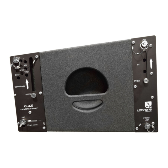
Page 16: Guide Links
Operation Manual Guide links CLA21 GUIDE LINKS ARM CLa21 is equipped with four captive guide links arms that link to adjacent units of CLa21 or SW-18VR in flown and groundstacked arrays. Located at the top corners of the cabinet, the guide links arms extend up and into the link slots of the cabinet above it (or into the link slots of the THV21-18VR). - Page 17 Rigging Assembly Guide CLA21 SPLAY ANGLES Front guide links arms attach at splay angles of 0 or +4 degrees. However, the front guide links should almost always be attached at 0 degrees, to ensure that coverage between linked cabinets is continuous. When attached at 0 degrees, the front guide links arms act as a pivot point between the linked CLa21s, with the splay angle between the units determined by the rear guide link positions.
- Page 18 Operation Manual Wide splayed angles of 9 to 15 degrees should only be used for downfill coverage, or for steering coverage away from structures like balconies. The rear guide links arms determines the vertical splay angle (whether stacked or flown), as a function of the hole where the pin is attached.
- Page 19 Rigging Assembly Guide When the front links guide are attached at +4 degrees, the pins must be inserted in the holes which the splay angles are labeled in brackets. The splay angles listed on the guide link labels are for relative angles between the center axes of the linked units.
- Page 20 Operation Manual Fig. 10 Guide link arm (Exposes) attached at 6 degrees, fixed position.
- Page 21 Rigging Assembly Guide SW-18VR GUIDE LINKS ARM When the SW-18VR is equipped with the TRK-18VR rigging kit, it includes six captive guide links arms and six mating link slots that link to adjacent units in flown and groundstacked arrays. Located at the top of the cabinet, links arms extend up and into the link slots of the cabinet above it, or into the link slots of the THV21-18VR grid, making it easy to link cabinets once they are stacked.
- Page 22 Operation Manual Fig. 12 Flown SW-18VR with CLa21 at the bottom. The SW-18VR's four corner link slots on the bottom of the cabinet must be use to link with another flown SW-18VRs. The front and middle link slots must be use lo link with a CLa21 loudspeakers when flying CLa21s below the SW-18VR.
-
Page 23: Flying A Cla21 Standalone Array
Rigging Assembly Guide SW-18VR SPLAY ANGLES Front and rear Guide links arms attach at angles of 0 and 3 degrees, thereby allowing curved arrays for the SW-18VR. Because the SW-18VR Guide links arms are symmetrical, curved arrays can also include cardioid configurations. Fig. - Page 24 Operation Manual CAUTION: Always use the quick-release pins included with the THV-21/18 grid to secure the attached CLa21 or SW-18VR. 2. Place a full dolly of CLa21 loudspeakers at the rigging location and remove the soft cover. 3. Check the inter-enclosure connections (repeat for each side): a.
- Page 25 Rigging Assembly Guide Fig. 17.a CLa21 Setting the front arm Fig. 17.b CLa21 Setting the rear arm c. Remove the four quick-release pins from the THV21-18VR, put the THV21-18VR over Array by aligning the four rigging points, and secure by re-inserting the 4 quick-release pins Fig.
- Page 26 Operation Manual Fig. 19 CLa21 Fixed to 6 degree 6. Place another full dolly at the rigging location and direct the front face of the array towards the audience 7. On top cabinet repeat step 4a (repeat for each one) 8.
- Page 27 Rigging Assembly Guide Fig 21 Example of CLa21 Standalone array.
-
Page 28: Flying A Sw-18Vr/Cla21 Mixed Array Or Sw-18Vr Standalone Array
Operation Manual Flying a SW-18VR/CLa21 mixed array or SW-18VR standalone array 1. Place a THV21-18VR at the rigging location. Placed directed towards the audience. Attach the shackle(s) to the desired pick-up point. Fig. 22 THV21-18VR Grid CAUTION: Always use the quick-release pins included with the THV-21/18 grid to secure the attached CLa21 or SW-18VR. - Page 29 Rigging Assembly Guide a. insert quick-release pins in the 0-degrees position into the rear guide link arms of SW-18VR below b. lift the stack and insert quick-release pins in the 3-degrees position into the front guide link arms of SW-18VR 8.
- Page 30 Operation Manual b. For the top cabinet on the floor, remove the stowed front guide link arms and re-connect them to the desired angel attachment, so they extend up and into the flown cabinet’s front link slots. Pin the front guide link arms to the flown cabinet with the previously removed quick-release pins.
-
Page 31: Groundstacking With The Thv21-18Vr Grid
Rigging Assembly Guide Groundstacking with the THV21-18VR Grid A CLa21 array must be stacked onto an THV21-18VR grid. The grid increases the array stability. With some restrictions, the THV21-18VR grid safely groundstacks up to: A grid stacked array can be composed of a maximum of 8 CLa21 enclosures along with all loudspeakers cables. -
Page 32: Configuring Guide Link Arms For Thv21-18Vr
Operation Manual To groundstack SW-18VR with THV21-18VR grid, the SW-18VR must be equipped with the TRK-18VR rigging kit. Fig. 26 THV21-18VR with SW-18VRs Configuring guide link arms for THV21-18VR The configuration of the THV21-18VR grid’s guide link arms, which can be set to A, B, or STOW, determines the angle of attachment for the loudspeaker at the bottom of the groundstack. -
Page 33: Grid Orientation And Groundstacks
Rigging Assembly Guide Table list the available angles of attachment for groundstacked CLa21 and SW-18VR Resulting Angle of Attachment for Groundstacked Front arm set to Rear arm set to CLa21 SW-18VR CLa21+ANGEXT CLa21+PullBack 0º -4º -10,7º/-14,7º -7,7º +4º 0º -6,7º/-10,7º -3,7º... -
Page 34: Adding Groundstack Tilt With The Optional Angext Arm
Fig. 30 THV21-18VR grid for groundstack with CLa21 Adding Groundstack tilt with the optional ANGEXT arm The Tecnare® CLa21 – ANGEXT are two angle arm extensions providing extra 10,7° or 14,7º downwards site angle for the bottom CLa21 in stacked configurations. - Page 35 Rigging Assembly Guide 2. Link CLa21 to THV21-18VR: a. Lift up CLa21 and turn its guide link arms downwards and front face towards the audience. b. Insert the two front link slot of CLa21 into the guide links arms of THV21- 18VR.
-
Page 36: Groundstacking Cla21 On Sw-18Vr
Operation Manual Groundstacking CLa21 on SW-18VR A SW18-VR/CLa21 mixed array or a SW-18VR standalone array can be stacked directly on the ground (ground stacked array) or onto an THV21-18VR Grid. Figure 62 shows a mixed array of each type. GroundStacking array: To be stacked on a perfectly horizontal and regular surface ONLY THV21-18VR Stacked array: Increases CLa21 array site angle... - Page 37 Rigging Assembly Guide Fig. 34 Linking SW-18VR to THV21-18VR 6. Connect the magnetic quick-locks pins to the THV21-18VR rigging point. 7. Attach a second SW-18VR to the first SW-18VR as follows: a. Place SW-18VR at the rigging location. b. Orient the front grill towards the audience or backwards. c.
-
Page 38: Pull-Back Pb-Cla21
Operation Manual 9. If the array is intended to be a SW-18VR standalone array, check if the stacking platform is still horizontal and secure the system to a fixed point using a ratchet strap or any other applicable material (not provided). Pull-back PB-CLa21 For applications requiring extreme array downtilt that are not possible with adjustments to the motors attached to the grid, the optional PB-CLa21 pull-back frame can be connects to the... -
Page 39: Groundstacking Cla21 On Sw-18Vr
Rigging Assembly Guide Groundstacking CLa21 on SW-18VR The CLa21 pull-back frame can be used to add 3 degrees of downtilt to CLa21s groundstacked on top of the SW-18VR. To achieve the downtilt, the pull-back is placed between the bottom CLa21 and the SW-18VR’s middle guide links. The downtilt from the pull-back is added to the tilt achieved with the SW-18VR’s middle guide links (see next table). -
Page 40: Twd21 Wooden Transport Dolly
Operation Manual TWD21 Wooden transport Dolly The TWD-21 touring carts safely transports up to four CLa21s, making it easy to assemble and disassemble arrays in blocks of four cabinets. The entire cabinet assembly stored in the cart can be directly connected to the THV21- 18VR grid or mounted below already suspended CLa21 or SW-18VR cabinets. -
Page 41: Twd21 Wooden Dolly Dimensions
Rigging Assembly Guide TWD21 wooden dolly dimensions Fig. 39 TWD21 Wooden dolly Dimensions TWD21 Wooden dolly Weight: 5.5 kg. (12.12lbs.) -
Page 42: Safety Guideline For The Twd21 Wooden Dolly
Operation Manual Safety guideline for the TWD21 wooden dolly ▪ Do not stack more than four cabinets on the TWD21 wooden dolly. ▪ When transporting CLa21 stacks, pack them front-to-front or back-to-back so the rear plates do not face toward grille frames in neighboring stacks. While the CLa21 rear plate do not extend beyond the edge of the wooden dolly, rapid accelerations and stops could cause stacks to tip toward neighboring stacks, potentially damaging grille frames. -
Page 43: Twd-18Vr Wooden Transport Dolly
Rigging Assembly Guide TWD-18VR Wooden transport Dolly The TWD-18VR wooden dolly safely transports up to three SW-18VRs, making it easy to assemble and disassemble arrays in blocks of three cabinets. The TWD-18VR can also be used to support SW-18VRs in groundstacked configurations. Fig. - Page 44 Operation Manual SW-18VR cabinets need not be equipped with the TRK-18VR rigging kit for transport with the wooden dolly. The loudspeaker skids ensure that cabinets stack cleanly on the caster frame. However, to avoid tipping, straps (not included) should be used when transporting cabinets.
- Page 45 Rigging Assembly Guide The THV21-18VR grid can travel installed on top of SW18VR stacks on the TWD-18VR wooden dolly. When transporting the THV-18VR grid on top of SW-18VR stacks on the TWD-18VR wooden dolly, to avoid colliding the grid with other SW-18VR stacks, attach the grid to the top SW-18VR cabinet with the cabinet’s front and rear guid links arms set to 3 degrees, so the grid is effectively raised 13mm (½”) above the stack.
-
Page 46: Twd-18Vr Wooden Dolly Dimensions
Operation Manual TWD-18VR wooden dolly dimensions Fig. 44 TWD-18 VR Wooden Dolly dimensions TWD-18VR Wooden Dolly Weight: 5.8 kg. (12.78lbs) -
Page 47: Safety Guideline For The Twd21 Wooden Dolly
Rigging Assembly Guide Safety guideline for the TWD21 wooden dolly ▪ Do not stack more than three cabinets on the TWD-18VR Wooden Dolly. ▪ When transporting SW-18VR stacks, pack them front-to-front or back-to-back so the rear plates do not face toward grille frames in neighboring stacks. While the CLa21 rear plate do not extend beyond the edge of the wooden dolly, rapid accelerations and stops could cause stacks to tip toward neighboring stacks, potentially damaging grille frames. -
Page 48: Service, Inspection & Maintenance
Service, Inspection & Maintenance General Service If all components in the Tecnare® system are used as it is described in this manual they will remain fully operational over the enclosures’ life. These has been designed to withstand the most rigorous and demanding environments. However, through regular operation it may still be necessary to replace acoustical, electronic and mechanical components. - Page 49 Rigging Assembly Guide...
- Page 50 Operation Manual...
- Page 51 Exel Acoustics. Tecnare and PCC-Net are trademarks of Exel Acoustics SL. Podware, System Engineer, BvNet, Smaart and all third-party trademarks mentioned herein are the property of their respective trademark holders.
- Page 52 EXEL ACOUSTICS SL CL Encinar, 282 - Pol. Ind. Monte Boyal 45950 Casarrubios del Monte (To) Spain support@tecnare.com www.tecnare.com - www.facebok.com/tecnare (T): +34 918 170 110 - +34 918 171 001 (F): +34 918 183 053 rev.:1.00 2017...
Need help?
Do you have a question about the EXEL ACOUSTICS SL ARRAY Series and is the answer not in the manual?
Questions and answers