Advertisement
Quick Links
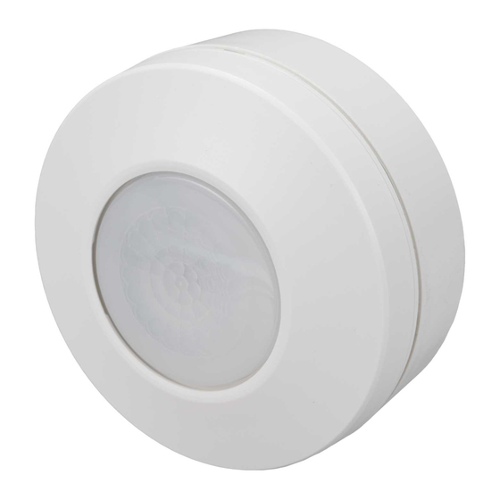
PMSC - Occupancy Sensor
TECHNICAL DATA
Rated voltage: 230V~ 50Hz
Load:
● Load 1(↑) for Ligh�ng
Incandescent: 2200W
High voltage Halogen: 2200W
Low voltage Halogen: 1200VA/1000W
Fluorescent: 1200VA/140uF
Energy saving or LED lamp: 800VA/600W
LED lamp : max. 13W(Philips) x 46pcs
LED driver : max.400W (PF=0.5)
● Load 2(C1, C2) for HVAC (Dry contact N.O.):
Max. 1A for 5-250VAC (cosφ=0.4) or
Max. 5A for 5-250VAC (cosφ=1) or
Max. 5A for 5-30VDC
Ingress Protec�on:
IP20 for flush mount with European standard junc�on box
IP20 for flush mount with spring clip box
IP54 for surface mount with surface mount box
Opera�ng Temperature:
-20°C ~ 45°C
PACKAGE CONTENTS
Detector
Fixing plate
x 1
x 1
● Flush box c/w spring clips x 1
Plug
x 2
Lens shield
Instruc�on manual
x 1
x 1
● Surface mount box x 1
Plas�c plug
Wood screw
x 2
1
PRODUCT DESCRIPTION
Features
This series is available in various moun�ng ways, e.g. surface mount and flush mount both applicable,
and can fit to a standard 1 gang pa�ress box. The accessories surface mount box and back cover with
spring clips to meet different moun�ng requirement. A red LED indicator is equipped for Test Func�on.
Dimension
● Detector
49
● Detector with surface mount box
Ø105
OPERATION AND FUNCTION
Detec�on Range:
Approx. Φ9m/360° at 2.5m height, 20°C.
x 2
Ø105
● Detector with flush mount spring clips
H 2.5m
2
Ø66
Advertisement

Subscribe to Our Youtube Channel
Related Manuals for E-matic PMSC

Summary of Contents for E-matic PMSC
- Page 1 PRODUCT DESCRIPTION Features PMSC - Occupancy Sensor This series is available in various moun�ng ways, e.g. surface mount and flush mount both applicable, and can fit to a standard 1 gang pa�ress box. The accessories surface mount box and back cover with spring clips to meet different moun�ng requirement.
-
Page 2: Installation And Wiring
INSTALLATION AND WIRING Time Adjustment: Time 1 (for ↑) with 7 steps adjustable: (Pulse)-30s-1m-5m-15m-30m-Test Time 2 (terminals C1, C2) with 7 steps adjustable:10s-1m-5m-10m-20m-30m-60m ● Please disconnect power completely and read the en�re instruc�on manual carefully before installa�on and retain for future reference. Note: The detector LED indicator will blink 3 �mes when the poten�ometer is adjusted and the ●... - Page 3 Installa�on Procedure ● Ceiling flush mount with either a 1 gang or round pa�ress box (not supplied) Cap�ve screw 1. Twist to remove the decora�ve frame. Drill a hole with =68mm on the 2. Strip between 6 - 8mm of cable sheathing for wiring. (See FIG.4). Please refer to illustra�on of ceiling FIG.1~3 for correct wiring connec�ons.
-
Page 4: Troubleshooting
Lens Shield Undesired detec�on areas can be shielded off by fixing the enclosed lens shield onto the lens. 6 - 8mm Trim the lens shield with scissors either horizontally or ver�cally un�l the desired detec�on area Earth is obtained. 30 - 35mm Rubber washer FIG.11... - Page 5 E-Ma�c Energy Management Solu�ons 10 Sandersons Way, Marton, Blackpool, Lancashire, FY4 4NB Email: enquiries.ema�c@adivision.co.uk Web site: www.e-ma�c.co.uk Environment: Please do not dispose the packaging as unsorted waste, use the recycling facili�es provided by your local authori�es. When the sensor comes to the end of its life or you choose to update or upgrade by replacing it, then do not dispose with your normal household waste.
Need help?
Do you have a question about the PMSC and is the answer not in the manual?
Questions and answers