
Related Manuals for Hoppecke Xchange MU


Summary of Contents for Hoppecke Xchange MU
- Page 1 ORIGINAL OPERATION MANUAL manual battery replacement unit trak | Xchange MU Modell: MU Operation Manual_MU_HPL_En...
-
Page 2: Table Of Contents
Periodic maintenance ....................8 Refurbishment of the unit ..................9 Occupational health and safety requirements ..............9 IT IS STRICTLY PROHIBITED TO: ................. 9 Spare parts list ......................10 Warranty ........................10 contact ..........................11 HOPPECKE Service: .....................11 Centrale - Brilon: ....................11 Operation Manual_MU_HPL_En... -
Page 3: General Remarks
1 General remarks 1) This manual is part of the unit and must: a. be accessible to maintenance and operation personnel at all times; b. be read before using the unit; and c. be complied with during operation. 2) The user is obligated to observe the health and safety requirements contained in this documentation and to comply with all applicable occupational health and safety regulations that are in force at the facility. -
Page 4: General Description
2 General description The MU manual battery replacement unit, hereinafter referred to as unit, is designed solely for the replacement and installation of batteries that power electric transport trucks of the weight and size (listed below) from a transport truck (including a forklift) into the compartment of the unit. -
Page 5: Operation Instruction
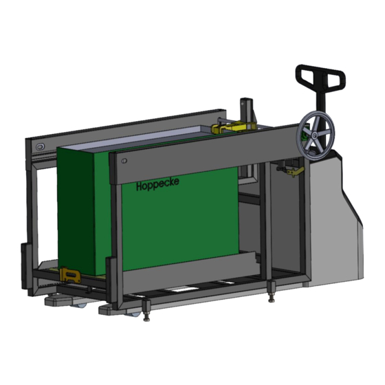
3 Operation instruction The design of the MU type battery changing unit is shown in the figure below. Fig. 1 Design of the unit The unit is used to replace and transport batteries with the dimensions specified above. It consists of a battery frame (compartment) with a roller conveyor in the lower part and a mechanism for introducing batteries into the compartment. -
Page 6: Loading Batteries Into The Mu
Loading batteries into the MU • Check the overall technical condition of the unit and that its various parts are in a perfect working order. Also check all connections of the components of the conveyor system for any play. Never use a damaged unit. •... -
Page 7: Unloading Batteries From The Mu
Unloading batteries from the MU Discharge the battery from the MU in the same way but in the reverse order. • To remove the battery from the unit, place the front surface of the battery on a rack or a truck, checking the heights of the rollers and the bottom of the battery (they must be at the same level), and checking the alignment of the sides of the battery before performing the transfer. -
Page 8: Basic Maintenance
4 Basic maintenance NOTE: Failure to comply with the following recommendations may contribute to damage of the MU and an accident. Observing the following instructions will considerably reduce the wear and tear of individual parts of the roller table and will therefore have a decisive impact on the reliability and service life of the entire conveying unit. -
Page 9: Refurbishment Of The Unit
Refurbishment of the unit The unit should be refurbished once a year or after 6,000 hours of unit operation, whichever occurs earlier. Refurbishment activities: • tighten all bolts and nuts, and replace them if necessary; • clean the entire system and the mating surfaces; •... -
Page 10: Spare Parts List
6 Spare parts list Quantity Manufacturer Name Parameters Type [pcs] Supplier Adjustment feet M22, L=80 mm HOPPECKE Poland Support roller Ø 48.3, L=650 mm, R48/650 HOPPECKE Poland Chain 08B1 ½ roller 3.4 m HOPPECKE Poland Toothed wheel 16Z 08B-1 DIN 8192... -
Page 11: Contact
8 contact HOPPECKE Service: In the event of a malfunction, contact Hoppecke Service: Tel: +49 (0) 800 246 77 32 Fax: +49 (0) 2963 61-543 E-Mail: service@hoppecke.com Please have the data on the nameplate ready if you have any questions or problems.
Need help?
Do you have a question about the Xchange MU and is the answer not in the manual?
Questions and answers