Table of Contents
Advertisement
Quick Links
Advertisement
Table of Contents

Subscribe to Our Youtube Channel
Related Manuals for Maquet Servo ventilator 900 C


Summary of Contents for Maquet Servo ventilator 900 C
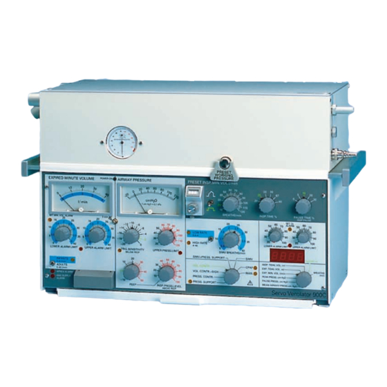
- Page 1 Servo ventilator 900 C/D/e Service Manual...
-
Page 2: Table Of Contents
Index ....52 This Service Manual is intended for Servo Ventilator 900 C, Block diagram ....56 D and E. - Page 3 Product information program This Service Manual is a part of a comprehensive in- formation program for Servo Ventilator 900 C/D/E. The program is planned to contain the following: Promotional and Scientific Publications Brochure Servo Ventilator Application Product Leaflet Reprints Concept...
-
Page 4: Introduction
Electronic unit SV 900 C Electronic unit SV 900 D Electronic unit SV 900 E Principle of operation The Servo Ventilator 900 C/D/E consists of two sepa- The electronic unit comprises three controlling rate units. systems, two for regulation of inspiration and one for The pneumatic unit comprises the gas conduction regulation of expiration. - Page 5 Introduction Feedback control (= regulation system) D-action gives a speed-up positioning reaction at fast Each of the controlling systems comprises its PID- changes (in the ACTUAL VALUE). controller, (P=Proportional action, I=Integral action and The actual value from the TRANSDUCER in use is D=Derivative action), as shown in the picture.
-
Page 6: Principle Diagram
Principle diagram Reference level Monitoring The main block REFERENCE LEVEL generates the The monitoring of all values that are displayed on the panel DESIRED VALUE for each regulating system, corre- meters and the digital display takes place in this main sponding to the settings on the front panel. - Page 7 Principle diagram & = Not valid for SV 900 E = Not valid for SV 900 D...
-
Page 8: Pneumatic Unit
Pneumatic unit Gas flow through the ventilator The gas is filtered concentration in the gas is The gas flow to the patient measured is measured The gas supply is regulated so The safety valve opens if the that a constant filling volume is bellows is overfilled or if the maintained in the bellows pressure in the bellows exceeds... -
Page 9: Gas Supply
Pneumatic unit Gas supply The lower gas inlet is used for high pressure gases 250- When an anesthesia vaporizer is used, the gas supply 700 kPa). The inlet can be connected either via a gas mixer unit has a different construction with three nipples. For or directly to the hospital central gas supply, to gas bottles further information, see the Operating Manual for the or to a compressor. -
Page 10: Bellows And Spring Assembly
Pneumatic unit Bellows and spring assembly The bellows are placed in a double coil spring set between two metal plates. The lower plate is movable and spring tensioned. The upper plate acts as a lid, which is firmly positioned above the bellows. A double coil spring set is arranged to give a constant pressure to the bellows, independent of the plate position. -
Page 11: Gas Supply Unit
Pneumatic unit Gas supply unit The gas supply unit contains an on-demand valve for the high pressure gas, a controlled inlet valve, two one-way valves, the O cell holder and a bacteria fil ter. Normally, the high pressure inlet is used and the bellows are filled through the controlled inlet valve, a one- way valve and the bacteria filter. -
Page 12: O 2 Cell
Pneumatic unit cell The O cell used in the ventilator gives an output vol tage proportional to the partial pressure of O at the cell. At constant sum of barometric pressure and WORKING PRESSURE (and constant temperature), the output voltage is proportional to the relative O CON CENTRATION. - Page 13 Pneumatic unit Relief/safety valve for gas evacuation A special reief/safety valve has to be used for gas evacuation. For detalíls, see corresponding Operating Manual. The relief/safety valve may be opened in two ways. Firstly, if the bellows tend to overfill, a metal rod will push the lever to let out excess volume (surplus func tion).
-
Page 14: Flow Transducer
Pneumatic unit Flow transducer The inspiratory and expiratory flow transducers have the same construction. The gas flows through the flow transducer in two parallel channels, one large main channel, and one small measuring channel. The main channel is fitted with a wire mesh net, the resistance of which causes a certain proportion of the gas to flow through the measuring channel. -
Page 15: Pressure Transducer
Pneumatic unit Pressure transducer The pressure transducers in the inspiratory and expi ratory channels are of the same type. The gas pressure acts upon a silicone rubber mem brane into which is moulded a strain gauge of the same type as in the flow transducers. The strain gauge resistors are connected as a part of a Wheat stone bridge, the other part of which is situated on the TRANSDUCER INTERFACE board (PC 765). -
Page 16: Inspiratory Valve And Step Motor
Pneumatic unit Inspiratory valve and step motor The inspiratory valve is operated by the step motor via the logarithmically slotted cam and the lever arm. When the step motor is in operation, a ball bearing at the end of the lever arm travels in the slot. The lever arm squeezes the inspiratory valve tube against a fixed arm. -
Page 17: Expiratory Valve And Pull Magnet
Pneumatic unit Expiratory valve and pull magnet The expiratory valve comprises a pull magnet acting on a lever arm which squeezes a silicone rubber valve tube against a fixed arm. The valve will close when the magnet is activated. When the supply current to the magnet is removed, the valve will open fully be cause of the spring. -
Page 18: Transducer Interface
Pneumatic unit Transducer interface (PC board no 11) This PC board comprises the preamplifiers for INSP. FLOW and EXP. FLOW, the amplifiers for AIRWAY PRESSURE (I), AIRWAY PRESSURE (E) and O CONCENTRATION. The INSP.FLOW WORKING POINT INDICATOR, EXP.FLOW WORKING POINT INDICATOR and the 6.8V REGULATOR and its 6.8V REGULATOR MONITOR are also included on this PC board. -
Page 19: Principle Of Operation
Electronic unit – Principle of operation The electronic unit contains the various electronic circuits for regulation and monitoring. A general description is found in chapter Introduction and the following chapter comprises a detailed description of the PC boards included in the electronic unit. -
Page 20: Reference Level Generation
Electronic unit – Reference level generation General The front panel settings are converted to reference level signals for the regulating systems. - Page 21 Electronic unit – Reference level generation Description of block diagram The text also refers to the circuit diagrams. Insp. press. level generation (PC board no 5) The input signal is the command value INSP. PRESSURE LEVEL SET (0-2.5V) from the front panel knob INSP. PRESS LEVEL ABOVE PEEP (0-100 cm H O).
- Page 22 Electronic unit – Reference level generation Ref. level adjust (front panel; INSP. TIME % selector) In this block, the constant (normally+5V) value from INSP. MINUTE VOLUME REF. LEVEL is converted into INSP. TIME ADJUSTED REFERENCE LEVEL by the voltage divider on the front panel selector. The square wave reference signal as well as the accelerating flow reference signal is inversly propor tional to the preset INSP.
-
Page 23: Regulation Of Inspiration
Electronic unit – Regulation of inspiration General The regulation of inspiration is done by means of the FLOW or PRESSURE SERVO LOOP depending on selected mode. The actual values for the controllers in these loops come either from the inspiratory flow transducer or the pressure transducers. - Page 24 Electronic unit – Regulation of inspiration...
- Page 25 Electronic unit – Regulation of inspiration Description of block diagram Volume compensation selector (PC board no 5) The text also refers to circuit diagrams. The actual value from either MAN. VENT. VOLUME COMPENSATOR or the common VOLUME Insp.flow linearization (PC board no 5) COMPENSATOR is choosen (by V25:6,11) in this stage.
- Page 26 Electronic unit – Regulation of inspiration Start insp. time marker (PC board no 5) Insp. pressure ref. level (PC board no 5) A pulse is generated at the beginning of the inspira tion The block outputs are INSP. PRESSURE REFERENCE time, This pulse is used for the derivating circuit in the LEVEL (V25:3) and the negative going INSP.
- Page 27 Electronic unit – Regulation of inspiration Direction & speed selection End position protector (PC board no 6) (PC board no 6) The purpose of the END POSITION PROTECTOR (V27) is to stop the VOLTAGE CONTROLLED OSCILLATOR when This is a multiplexer and the output signals are direc tion the step motor is at either of the two end positions and and speed.
-
Page 28: Timing
Electronic unit – Timing General The circuits in the main block TIMING deliver signals of fundamental significance for the respiratory cycle, i.e. the inspiratory phase (INSP. TIME), the pause pe riod and the expiratory phase (EXP. TIME), see the diagram below. The INSP. - Page 29 Electronic unit – Timing “MODE” In the entire BLOCK DIAGRAM, the designation MODE represents one or more of the following 13 output signals from the MODE CONTROL BLOCK: PRESS.REG.INSP TIME PRESS.REG.CONDITION PRESS.SUPP.MODE SET (LO) PRESS. CONTR. MODE SET (LO) VOL. + SIGH MODE SET (LO) VOL.
- Page 30 Electronic unit – Timing Description of block diagram Insp. time & expo time multiplexer (PC board no 3) The text also refers to circuit diagrams. This block is controlled by a MODE-signal. In manual Clock pulse generator (PC board no 3) ventilation, the signals from the INSP.
- Page 31 Electronic unit – Timing End insp. indicator (PC board no 5) Man. vent. timing (PC board no 7) In all modes which include spontaneous breathing. This stage receives the AIRWAY PRESURE (I) signal from (PRESS SUPPORT, SIMV and SIMV + PRESS. SUPPORT the inspiratory pressure transducer.
- Page 32 Electronic unit – Timing Start insp. & end insp. conditions, and the front panel settings on which they depend The start insp. conditions (V=ventilator and The end insp. conditions (0-5) are monitored in the P=patient) are monitored in the following blocks: following blocks: INSP.
-
Page 33: Monitoring
Electronic unit – Monitoring General The monitoring subsystem of the Servo Ventilator 900 C/D/E is used for continuous monitoring and indi- cation, via the front panel meters, of the pressure and flow signals. The expiratory flow transducer continuously meas ures the expiratory flow. - Page 34 Electronic unit – Monitoring...
- Page 35 Electronic unit – Monitoring Description of block diagram The signal MINUTE VOL. ALARM UNSET activates a flashing yellow light, SET MIN. VOL. ALARM on the front The text also refers to circuit diagrams. panel via the block ALARM LAMP DRIVER. Set O alarm limits (PC board no 9) Exp.
- Page 36 Electronic unit – Monitoring 2 minute timer (PC board no 6) Timing & supply voltage monitoring (PC board no 9) The input signals are AUDIO ALARM TURN OFF (LO) from the front panel pushbutton OFF 2 MIN and COUN TER In case of TIMING FAILURE, (from TIMING MONITORING) RESET from (R 80) MODE CHANGE INDICATOR.
- Page 37 Electronic unit – Monitoring Trig. level monitoring (PC board no 4) Upper pressure monitoring (PC board no 4) The signal PATIENT TRIG. (V14:14/L53) and TRIG. LAMP (V22:16), will both be high each time the actual value The input signals are HIGH PRESSURE STOP INSP., the AIRWAY PRESSURE (E) falls below the reference value actual values AIRWAY PRESSURE (I) and (E) and the TRIG.
- Page 38 Electronic unit – Monitoring Airway pressure panel meter Ripple reduction (PC board no 7) The panel meter for AIRWAY PRESSURE displays the This is a special low pass filter, creating a stable output inspiratory or expiratory pressure, depending on the value (V34:5), EXP.
-
Page 39: Regulation Of Expiration
Electronic unit – Regulation of expiration General The pressure signal from the pressure transducer in the expiratory channel is compared with the pre set PEEP level, and a difference results in a correction signal to the expiratory valve to maintain the set PEEP level. - Page 40 Electronic unit – Regulation of expiration Description of block diagram Pull magnet driver (PC board no 4) The driver stage converts the pulses into a current through The text also refers to the circuit diagrams. the pull magnet coil. The pull magnet keeps the expiratory valve closed during inspiration and pause.
-
Page 41: Voltage Supply
Electronic unit – Voltage supply General The Servo Ventilator 900 C/D/E can be connected to mains 110, 120, 220 or 240 V AC 50/60 Hz with a pro tective ground. (A special version for 100 V AC is av ailable) . -
Page 42: Input/Output
Electronic unit – Input/output General At the rear panel of the ventilator, there are three 15-pole Cannon sockets for AUXILIARY EQUIPMENT, a 25-pole Cannon socket (under a lid): CONTROL TER MINAL and a 37-pole Cannon socket with RECORDER OUTPUTS. Output buffers (PC board no 8) The output signals at the 15-pole and 37-pole Can non sockets are all (except the supply voltages) buffe red for security. - Page 43 Electronic unit – Input/output Recorder output The recorder output (37-pole Cannon), contains outputs for flow, pressure and some control signals. The outputs are adapted to Ming ograf recorders. The pins (1—37) of the connector are numbered 101—137 in the diagrams. Auxiliary equipment The 15-pole Cannon connectors, three in parallel, contains outputs for flow and pressure and some control signals.
-
Page 44: Electronic Unit
Disassembling Pneumatic unit Electronic unit... -
Page 45: Replacement Of Step Motor Assembly And Pull Magnet
Disassembling Step motor assembly and pull magnet... -
Page 46: Replacement Of Flow Transducer
Adjustments Replacement of flow transducer The FLOW TRANSDUCER spare part includes a sepa rate serial number label with the same number as the transducer. When replacing the FLOW TRANSDUCER, the connection plug label must be replaced with the new label. Adjustment of meters Z1 and Z2 •... -
Page 47: Replacement And Adjustment Of R5
Adjustments Replacement and adjustment of R5 Note – This adjustment is of vital importance for faultless operation. • Loosen (but do not remove) the Allen screws on the control knob. There are two screws on old knobs and one screw on new knobs. •... -
Page 48: Front Panel Potentiometer Adjustments
Adjustments Front panel potentiometer adjustments When exchanging any of the potentiometers on the front panel, use the table below for adjustments. • Connect a digital voltmeter between 0V (REF) (black wire) and the middle point of the actual potentiometer. • Adjust the potentiometer to the reading stated in the table. -
Page 49: Troubleshooting
Troubleshooting Before you start any troubleshooting, begin, ifpossi ble, If you use the block diagram and the principle by questioning the person reporting the fault. Ask about diagram (at the beginning of this Service Manual), the front panel control settings, gas connec tions, patient troubleshooting and servicing should not cause any connections and how the fault appe ared. - Page 50 Troubleshooting Action Malfunction Leakage in the relief valve in spite of normal working pressure The controlled inlet valve opens too soon. Check the opening positions as described in Adjustments, page 46. The gas supply to the ventilator via the upper (low- See Troubleshooting in the Operating Manual.
- Page 51 Troubleshooting Malfunction Action The preset inspiratory minute volume deviates considerably from the indicated expiratory minute volume. Leakage in ventilator. Perform a leakage test as described in the Operating Manual. Calibrate the ventilator as described in the Operating Malfunction in regulation of inspiration. Manua.
-
Page 52: Index
Index N.B. This is an index of all blocks used in SV 900 C/D/E. Function blocks In Included in main PC board Page alphabetic order block number Accelerating flow pattern Reference level 5 (PC 759) Active filter Regulation of expiration 4 (PC 758) Airway pressure (E)&(I) amplifier Transducer interface... - Page 53 Index Function blocks In Included in main PC board Page alphabetic order block number concentration transducer Pneumatic unit 3 (PC 757) Pause hold Timing – Peep compensator timing Regulation of expiration 4 (PC 758) Peep error calculator – with peep compensator Regulation of expiration 4 (PC 758) Peep level generation...
-
Page 54: Block Diagram
Electronic function block diagram... - Page 55 MAQUET for Surgical Workplaces, Cardiovascular and Critical Care. MAQUET for Surgical Workplaces, Cardiovascular and Critical Care.
Need help?
Do you have a question about the Servo ventilator 900 C and is the answer not in the manual?
Questions and answers