Advertisement
Quick Links
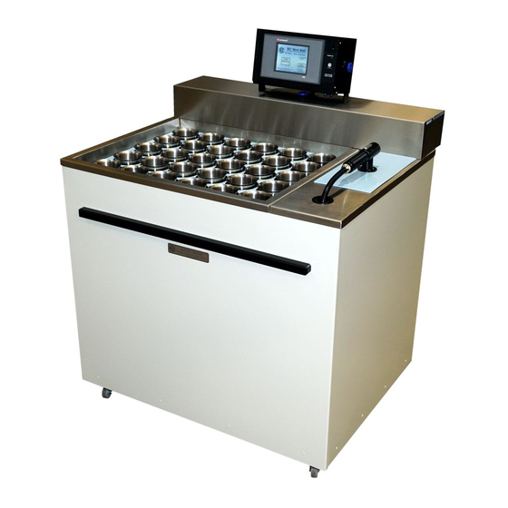
THE 'IEC' MASH BATH
This manual covers all models for 2019
FLOOR MODELS:
16, 20, 25 and 30 head.
Image shows 20 Head,
with 'touch panel' control
system and distilled
water storage and
dispensing.
Belts are no longer used
for stirrer drives.
Designed and Manufactured by :
.
I N D U S T R I A L
6 1 - 6 5
M c C l u r e
T e l :
6 1
M A S H B - 2 0 1 9 0 3 1 4 . d o c
Industrial Equipment & Control Pty. Ltd.
Melbourne
E Q U I P M E N T
S t .
T h o r n b u r y .
( 0 ) 3
9 4 9 7
2 5 5 5
E m a i l :
i e c @ i e c p l . c o m . a u
Australia.
&
C O N T R O L
3 0 7 1
M e l b o u r n e .
F a x :
6 1
( 0 ) 3
9 4 9 7
Mash Bath
Models 290 & 290/530
: belt free stirrer drive
BENCH MODELS:
6, 9, 12 and 16 head.
Image shows 9 Head,
with 'touch panel'
control system and
distilled water heating
tubes.
Belts are no longer
used for stirrer drives.
MASHB-2018-02-01.pdf
P T Y . L T D .
A u s t r a l i a
2 1 6 6
1 4 - M a r - 1 9
1
Advertisement

Related Manuals for IEC MASH BATH

Summary of Contents for IEC MASH BATH
- Page 1 Mash Bath THE ‘IEC’ MASH BATH This manual covers all models for 2019 Models 290 & 290/530 : belt free stirrer drive BENCH MODELS: 6, 9, 12 and 16 head. Image shows 9 Head, with ‘touch panel’ control system and distilled water heating tubes.
- Page 2 Mash Bath Bench models do not have distilled water storage or dispensing, but the special bath lids carry tubes to carry distilled water that heat with the bath and are used to add volume to the sample as required. Floor standing models have temperature controlled distilled water storage and a quick action dispensing system.
-
Page 3: General Description
Mash Bath GENERAL DESCRIPTION: A high quality, electronically controlled Mash Bath containing up to 8 selectable programs that relate bath temperatures with times. The IEC Bath is carefully designed to automatically perform the standard mash sequences as required by the various brewing, barley, malt and cereal industries, however its versatility permits it to be easily programmed for variations to these standard tests. -
Page 4: Fitting The Controller
All the larger sized floor mounted machines fit through standard width doorways. • IEC designs and manufactures a range of excellent Mash Baths: Floor mounting Mash Baths for 16, 20, 25 or 30 Pots with magnetic stirring and distilled water storage, temperature control and automatic dispensing. - Page 5 Electrical Services Required: Standard voltages listed below. Machines frequency can be either 50 or 60 Hz. Please contact IEC for other voltages if required. BENCH MOUNTING MODELS: SINGLE...
-
Page 6: Wire Colours
For gravity feed, the still should be mounted at least 1 metre higher than the Mash Bath so the head pressure is sufficient. Because of the low source pressure, the hose and the connection from the distilled water source should be large in diameter. -
Page 7: Electrical Connections
Mash Bath FOR MAINTENANCE AND TRADES: PREPARATION FOR CONNECTING: Remove all packing and ties that may be present for security of transport. Check the • machine generally for damage. Lift off the long rear cover (with controller disconnected) to expose the mains wiring •... -
Page 8: Outer Panels
Mash Bath OUTER PANELS: The outer panels of the machine have no screws. For removal, lift panel slightly and swing the bottom edge outwards. The front panel is fitted with a lifting rail for easy removal. While the first cycles are being run, always leave the front panel removed to observe any signs of wetness or leaks in hoses and pipework. - Page 9 Mash Bath CONTINUE INSPECTION: Inspect the machine further: Remove rear and front covers by lifting panels and allowing bottom edges to come forward. At the rear….. Observe the solenoid valves and hoses. These control mains water in and drain water out. The third hose is for the important overflow inside the bath that must be drained through a separate hose.
- Page 10 Mash Bath STARTUP: At this time, the machine should in position and connected to power and mains • water. Be sure the large drain hoses are down the drain facility pipe for a distance of say 30 cm. Be sure there are no loops, kinks or obstructions in these large hoses.
- Page 11 THE OPTIONS AVAILABLE. OVERVIEW ……………. A TYPICAL MASH: The Mash Bath is designed to accept a certain number of stainless steel pots through a special lid so they rest into the water bath. On the bench models, the smaller pots are manually filled with the correct volume of d/w that needs to be added to the mash part way through the program.
- Page 12 Mash Bath ADD D / WATER: This first alert (#1) sounds to advise the operator to fill each pot with the correct volume of distilled water at the same temperature as the bath so that the test can begin. The required initial volume of distilled water is displayed on the screen and, with a momentary press of the gun switch, this programmed volume at the correct temperature is added to each pot.
- Page 13 Mash Bath In EDIT mode, a GRAPH of the program is created and is visible to the operator as the information is entered into each step of the program. In running mode, the GRAPH of the selected program appears on the screen and progress along the graph is indicated by a visible cursor or ‘time-line’.
- Page 14 Mash Bath STIRRING OPTIONS: Normally the dry sample is not stirred during the preheat period and, after the distilled water has been added to the sample and GO has been pressed to cancel the HALT, the stirring begins and continues. The choices for stirring at any step are: YES.
- Page 15 RAM and the long life memory battery is also displayed on this screen On later models a button permits the optional complete draining of the mash bath before shutting down. When pressed the bath drains empty and the alert beeper sounds to advise the draining is complete.
- Page 16 Mash Bath ‘CNTRL’ display SELECTION to CNTRL: Provides manual control of some of the bath functions. In the case of a malfunction or an unwanted noise, magnetic stirrers banks can be turned off or be permitted to run. Bath filling and draining can be controlled.
- Page 17 Mash Bath DIAGNOSTIC 1 display D/W CNTRL to DIAG: This display is mainly for maintenance and fault finding. PLC inputs status is displayed with values of the controller’s internal temperature, the temp.sensors, the scan time, RAM status and battery status and ID info.is shown.
- Page 18 Mash Bath PROGRAM RUN display SELECT to ENTER: If the bath and d/w tank are both full, the selected program can be run. The graph displays to show the temperature and time relationship for each step. Press GO to begin. Heaters come on and ‘H’...
- Page 19 Mash Bath PROGRAM RUN – NOTES…. continued……… As the program progresses, a vertical cursor or ‘time-line’ is seen to move from left to right so that the current point on the graph can be seen. The program name, it’s number and the step number are all displayed.
- Page 20 Mash Bath INFO2 display This display contains notes to assist the operator. EXIT reverts to program run display. EDIT PROGRAM display Program is built from step0 up to final step or END. On step0, start C is 15 . ‘min’ (time) •...
- Page 21 Mash Bath STEP 2 display STEP2: The “start C” (45 C) is copied from the • “end C” of the previous step. It cannot be altered. Press “min” and set to 25. Press and set • “end C” to be 70 C.
- Page 22 Mash Bath STEP 5 display STEP5: The “start C” (25 C) is copied from the • “end C” of the previous step. It cannot be altered. Press “min” and set to ZERO. Press • and set “end C” to be ZERO. This means the END of PROGRAM.
- Page 23 Mash Bath EDIT PROG.NAME display This display permits editing, adding or removal of any program name. Press on the line you want to edit. A full • keyboard will appear with 3 alternative screens to choose characters. Print out the new name and press the •...
- Page 24 Mash Bath D/W TEMPERATURE display D/W TEMPERATURE:: For floor models, this display permits the distilled water temperature to have a small OFFSET applied to maximise accuracy. Use accurate thermometer in the d/w tank and adjust OFFSET so the tank temp.control matches the thermometer.
- Page 25 Mash Bath SPARE PARTS, SERVICE & MAINTENANCE: NOTE:: Either “Belt and Pulley” or “Belt Free” drive system can be used on any Mash Bath. Both types are described here: SPARE PARTS PROVIDED WHEN BELTS AND PULLEYS ARE USED FOR THE STIRRING SYSTEM: 1x Set of spare belts for each bank of magnetic stirrers.
- Page 26 Mash Bath For removal of the stirrer bank, see details above on belt removal. When the drive belt is moved to the spare motor, the old motor with pulley can easily be removed for replacement. and a small switch on the end of the PCB selects the spare motor to be active.
- Page 27 DC motor. Turn off the power to the machine. Remove the lid of the mash bath for access and also remove the long rear cover over the electrics. NOTE:: If the cable is disconnected from the Control Unit, it can remain mounted on the cover as the cover is lifted from the machine.
- Page 28 Mash Bath FAULT FINDING ASSISTANCE: Power will not go on. Master switch on side of cover not turned ON. • Switch on the control unit not switched ON. • Circuit breakers under main cover off or tripped. • No power to machine.
- Page 29 Mash Bath Bath floods OR will not drain down its overflow. Overflow drain hose from the machine kinked or blocked. • Overflow pipe set too high so that level is too high before overflowing down the • overflow pipe. During overflow or filling at the end of some program cycles, mains water pressure •...
- Page 30 CAUTION: S/Valve coil can burn out. NOTE:: For systems with pressurised distilled water, IEC can fit a higher pressure solenoid valve in the distilled water circuit. Will not dispense distilled water OR slow dispensing.
- Page 31 Mash Bath Distilled water tank wrong temperature. Distilled water tank should follow the same temperature as the bath so the distilled • water is always matching the temperature of the sample pots. After the topup volumes are dispensed (part way through the program), the d/w tank cools down for the next program start and the temperature will not be the same as the bath.
- Page 32 Mash Bath COMPONENT PARTS AND INFORMATION: RTD temperature probes: Supplier: Industrial Thermocouple Supplies Pty.Ltd. Melbourne Australia. OR Pyrosales Pty. Ltd. 1x 1/4" x 180mm long, S/S RTD probe PT100 single, compensated. 1x 1/4" x 430mm long, S/S RTD probe PT100 dual, compensated.
- Page 33 BS139 S70 Silicone Rubber. Stirrer to stirrer: BS154 E70 Ethylene Propylene rubber. Lid seals around pots: Special IEC seals for 500ml pots I N D U S T R I A L E Q U I P M E N T &...
- Page 34 Mash Bath Controller: Touch screen: Unitronics, Type: Vision 290 – 19 – B20B 24V.DC. H/w revision A. Version 4.7 (23). PLC (snap-on type): I/O module …. V200-18-E3/4XB All relay outputs, 3 amp. Audible Alert: Beeper, 24V.DC. Supplier: Switches Plus Pty.Ltd.
Need help?
Do you have a question about the MASH BATH and is the answer not in the manual?
Questions and answers