Table of Contents
Advertisement
Quick Links
SEL-734W and SEL-WCS
SEL Wireless Current Sensor (SEL-WCS)
Overview
Current Measurements
Date Code 20191014
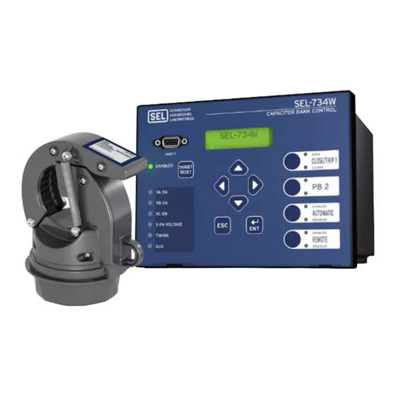
SEL-734W Wireless Capacitor Bank Control
and SEL-WCS Wireless Current Sensor
The SEL-734W Wireless Capacitor Bank Control is a system that includes the
controlling device (SEL-734W) and the line current sensors (8340). The sensors
report line in the current via radio transmission. The SEL-734W includes a radio
receiver used solely for the purpose of receiving the transmissions from the line
current sensors. A capacitor bank control uses measurements of voltage and cur-
rent on the distribution lines of an electric utility to determine if the distribution
of electric power can be made more efficient by connecting a capacitor from the
phase to the neutral conductors of the distribution system. Based on user-select-
able settings, the SEL-734W will drive the capacitor bank switches to connect/
disconnect the capacitors from the power lines of the distribution system. Opera-
tion of the SEL-734W is the same as the operation of the SEL-734B with the
exception of how the line currents are read.
The SEL-734B accepts wires carrying low-level voltages that are an analog rep-
resentation of the current in each of the power system conductors. These wires
are connected to sensors attached to the power lines, with the sensors converting
the current to low-level voltages known as low-energy analog (LEA) signals. For
information that is common to both the SEL-734B and the SEL-734W including
installation, operation, and settings, refer to the documents found at
www.selinc.com/products/734B. For information on how the SEL-734W and the
SEL-734B differ, refer to the sections below.
The SEL-WCS provides measurement of power line current both for the funda-
mental frequency and harmonic frequencies (up to the 15th). This sensor is pro-
vided in a package that is easy to mount using a hot stick and requires no wiring
to the capacitor bank control or to a power source. Power is harvested from the
magnetic field surrounding the power line when current is flowing. The
SEL-WCS operates without the use of a battery, eliminating that maintenance
concern while allowing for a smaller, simpler device. The SEL-WCS measures
the current and updates the SEL-734W periodically, making sure that it has
enough stored energy to complete the measurement and transmit the information
to the SEL-734W before beginning the measurement process. The SEL-734W
provides a measurement range of 2 A to 1000 A. The SEL-WCS is paired to an
SEL-734W by settings selections made on both devices.
Measurements are made by the sensor and sent to the SEL-734W about once
every 1.1 seconds or as harvested energy allows, whichever is slower. The
SEL-734W will use the last value transmitted in all reporting, calculations, and
actions involving the current until the next update of the current. If the
SEL-734W has not received a recognizable update within a certain timeframe,
the current value is set to zero and stays at zero until the next successful update.
A switch-selectable setting for the SEL-WCS tells the sensor whether it should
calculate the magnitude and phase values of the harmonics. By selecting the
Information Sheet
SEL-734W and SEL-WCS
Advertisement
Table of Contents

Subscribe to Our Youtube Channel
Related Manuals for Sel SEL-734W


Summary of Contents for Sel SEL-734W
- Page 1 SEL-734W will drive the capacitor bank switches to connect/ disconnect the capacitors from the power lines of the distribution system. Opera- tion of the SEL-734W is the same as the operation of the SEL-734B with the exception of how the line currents are read.
-
Page 2: Product Overview
Figure 1 SEL-WCS Key Components Shotgun Stick Loop and Spring The shotgun stick loop allows the SEL-WCS to be mounted on the line or removed from the line using only a shotgun stick. The springs simplify installa- tion on overhead lines and hold the SEL-WCS in position. See SEL-WCS Instal- lation for more information. -
Page 3: Integrated Radio
The control DIP switches inside the housing allow easy selection of the identifi- cation of each sensor. An SEL-WCS has a set of four DIP switches for a Network ID, two DIP switches for a phase ID, and a single DIP switch that determines whether an SEL-WSC sends the harmonic content information to the SEL-734W. - Page 4 SEL-WCS Settings Network ID settings The SEL-WCS has a 4-bit DIP switch that allows it to configure the Network ID. Table 2 shows the frequency associated with each Network ID. DIP switches SW1–SW4 shown in Figure 2 are for the Network ID.
- Page 5 (non-fault) conditions. It is used to increase the resolu- tion of the current reported to the SEL-734W. When in the > 200 A range, the resolution is approximately 0.25 A. For the lower range setting, the resolution is approximately 0.05 A.
- Page 6 Install the SEL-WCS on a distribution line by using an industry-standard shotgun stick. Step 1. Use a shotgun stick to grasp the hook eye on the side of the SEL-WCS and place the device on the line so that the opening hangs over the line.
-
Page 7: Safety Information
Safety Information Safety Information Regulatory Information DANGER The SEL-WCS is approved for use only with specific output power configura- tions that have been tested and approved. Modifications to the SEL-WCS, the Install fault transmitters and sensors in accordance with antenna system, and the power output that have not been explicitly specified by... -
Page 8: Dangers, Warnings, And Cautions
SEL-734W and SEL-WCS Information Sheet Date Code 20191014... - Page 9 Si vous n’êtes pas équipés returning this device and related SEL equipment for service. pour travailler avec ce type de composants, contacter SEL afin de retourner l’appareil pour un service en usine. Date Code 20191014...
- Page 10 47 CFR Part 15.107 Class A Ingress Protection Electromagnetic Compatibility Immunity IP67 Electrostatic Discharge: IEC 61000-4-2:2008 Clamp Range (SEL WCS) IEEE C37.90.3-2001 6.35 mm to 31.75 mm (0.25 in to 1.25 in) Discharges: Indirect: ±8 kV Dimensions Contact: ±8 kV Air: ±15 kV...
- Page 11 SEL-WCS Specifications Table 2 Certifications by Country Part Country Authority Reference Number U.S.A. and Colombia Canada Date Code 20191014 Information Sheet SEL-734W and SEL-WCS...
Need help?
Do you have a question about the SEL-734W and is the answer not in the manual?
Questions and answers