Table of Contents
Advertisement
Quick Links
Advertisement
Table of Contents

Related Manuals for ASTEL TR 101


Summary of Contents for ASTEL TR 101
- Page 1 TR 101 VIDEO TWISTED-PAIR RECEIVER OPERATING INSTRUCTIONS v1.0...
-
Page 2: Table Of Contents
CONTENTS Preface ................................ 3 Features ..............................3 Block diagram.............................. 3 Principle of operation........................... 3 Controls and connectors ..........................4 Connections ..............................5 Installation ..............................6 Appearance ..............................8 Specifications .............................. 8 This unit is produced to comply with Directive 89/336/EEC. -
Page 3: Preface
PREFACE The video twisted-pair receiver TR 101 is a and rough or fine gain adjustment at different correction amplifier with symmetrical input and the frequencies. There are LED1 and LED2 which standard asymmetrical video output. It is mounted indicate the power-on and the video signal error in in ABS casing. -
Page 4: Controls And Connectors
CONTROLS AND CONNECTORS (1) AC/DC POWER SUPPLY (12) TC 1 Power supply terminal block connector. HF gain adjustment trimmer. (2) TC 4 (13) TP 4 LF-III fine adjustment trimmer. LF gain adjustment trimmer. (3) LED 1 (14) SW1-SW16 Red LED for video signal error indicator. LF/MF/HF gain switches. -
Page 5: Connections
CONNECTIONS • Be sure to switch-off the power supply unit before connecting to other equipment. • Also refer to the instruction manual of the equipment to be connected. -
Page 6: Installation
INSTALLATION (1) Set the trimmer TP2 to the middle position. (2) Set the trimmer TP3 to the middle position. (3) Set the trimmer TP4 to the left. (4) Switch-off SW1-SW15, SW16 switch-on. (5) Set TC1, TC2, TC3 and TC4 to the minimal capacitance. (6) In the Table 1 select the CABLE (insulation, impedance Z , loss a ) and calculate the cable loss... - Page 7 adjusted sync. pulse TP4 adjustment TC1 adjustment Fig. 1: Sync. pulse correction Table 1 CABLE SECTION I (SW1-SW6) SECTION II (SW7-SW12) TYPE INSULATION a 5MHz/km 10 dB 20 dB 10 dB 20 dB Z L /Ω paper 51 dB 1 2 6 8 10 7 8 12 paper...
-
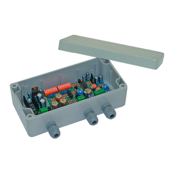
Page 8: Appearance
APPEARANCE SPECIFICATIONS Video input 0.12 - 2 Vpp (TP3) 45 Ω - 175 Ω (TP1) Input impedance 1 Vpp, 75 Ω Video output Freq. response 50 Hz - 5 MHz (-3 dB) > 70 dB, 50 Hz (TP2) Disturbance reduction Gain adjustment +6 dB...+60 dB at 5 MHz (SW1-SW16, TC, TP) Noise... - Page 12 ASTEL d.o.o., Dutovlje 138, 6221 Dutovlje, Slovenia Tel: +386 5 7310771, +386 5 7310772 Fax:+386 5 7310789 E-mail: sales@astel-cctv.com Web: www.astel-cctv.com...
Need help?
Do you have a question about the TR 101 and is the answer not in the manual?
Questions and answers