Table of Contents
Advertisement
Quick Links
Advertisement
Table of Contents

Related Manuals for ASTEL TRR 101


Summary of Contents for ASTEL TRR 101
- Page 1 TRR 101 VIDEO TWISTED-PAIR RECEIVER OPERATING INSTRUCTIONS v2.0...
-
Page 2: Table Of Contents
CONTENTS Preface ................................ 3 Features ..............................3 Block diagram.............................. 3 Principle of operation........................... 3 Controls and connectors ..........................4 Connections ..............................5 Installation ..............................6 Appearance ..............................8 Specifications .............................. 8 This unit is produced to comply with Directive 89/336/EEC. -
Page 3: Preface
PREFACE The video twisted-pair receiver TRR 101 is a impedance, symmetry, linear gain and rough or correction amplifier with a symmetrical input and fine gain adjustment at different frequencies. the standard asymmetrical video output. It is There are LED1 and LED2 which indicate the suitable to fit in a 19”... -
Page 4: Controls And Connectors
CONTROLS AND CONNECTORS (1) LED 1 (11) TC 1 Red LED for video signal error indicator. HF gain adjustment trimmer. (2) TC 4 (12) TP 4 LF-III fine adjustment trimmer. LF gain adjustment trimmer. (3) TC 3 (13) SW1-SW16 MF-III fine adjustment trimmer. LF/MF/HF gain switches. -
Page 5: Connections
CONNECTIONS • Be sure to switch-off the power supply unit before connecting to other equipment. • Also refer to the instruction manual of the equipment to be connected. -
Page 6: Installation
INSTALLATION (1) Set the trimmer TP2 to the middle position. (2) Set the trimmer TP3 to the middle position. (3) Set the trimmer TP4 to the left. (4) Switch-off SW1-SW15, SW16 switch-on. (5) Set TC1, TC2, TC3 and TC4 to the minimal capacitance. (6) In the Table 1 select the CABLE (insulation, impedance Z , loss a ) and calculate the cable... - Page 7 adjusted sync. pulse TP4 adjustment TC1 adjustment Fig. 1: Sync. pulse correction Table 1 CABLE SECTION I (SW1-SW6) SECTION II (SW7-SW12) TYPE INSULATION a 5MHz/km 10 dB 20 dB 10 dB 20 dB Z L /Ω paper 51 dB 1 2 6 8 10 7 8 12 paper...
-
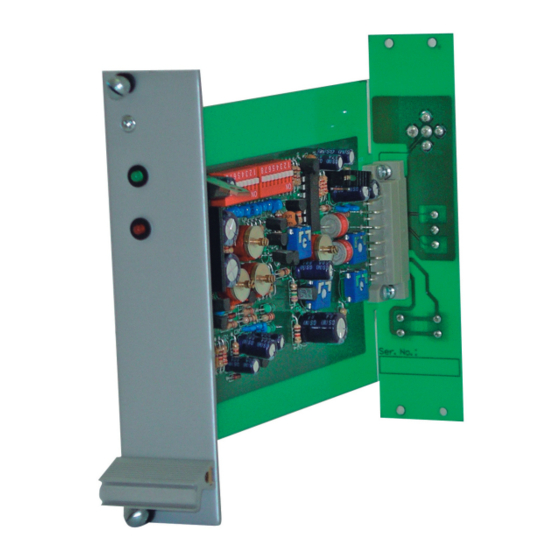
Page 8: Appearance
APPEARANCE SPECIFICATIONS Video input 0.12 - 2 Vpp (TP3) 45 Ω - 175 Ω (TP1) Input impedance 1 Vpp, 75 Ω Video output Freq. response 50 Hz - 5 MHz (-3 dB) > 70 dB, 50 Hz (TP2) Disturbance reduction Gain adjustment +6 dB...+60 dB at 5 MHz (SW1-SW16, TC, TP) Noise... - Page 12 ASTEL d.o.o., Dutovlje 138, 6221 Dutovlje, Slovenia Tel: +386 5 7310771, +386 5 7310772 Fax:+386 5 7310789 E-mail: sales@astel-cctv.com Web: www.astel-cctv.com...
Need help?
Do you have a question about the TRR 101 and is the answer not in the manual?
Questions and answers