Advertisement
Replacing the Interface Board
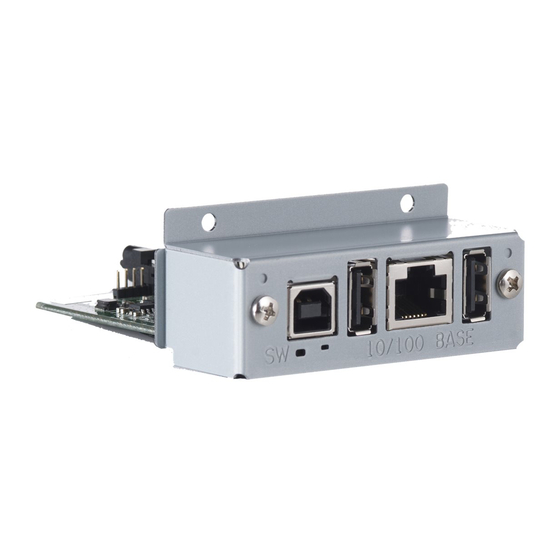
Use the following procedure to replace the interface board.
1. Replacing the Interface Board
(1) Make sure that the power cord is unplugged.
(2) Remove the two screws.
(3) Remove the interface board unit in the direction of the arrow.
(4) Slide the new interface board into the printer until it is firmly seated.
Note: Insert the interface board so that it connects with the connector.
(5) Secure the interface board using the two screws that you removed in step 2.
(6) Once the interface board has been connected, perform a self-print test before connect-
ing the Ethernet cable. Also, make sure that the printer recognizes the interface board.
When recognized: Prints "Interface: 100/10 BASE".
2. Setting the DIP Switches
The timeout time when acquiring the address from the DHCP/BOOTP server can be set us-
ing DIP switch No. 1. The factory default setting is 20 seconds. If DIP switch No. 1 is set to
ON, a timeout is not performed. If the address cannot be acquired due to the timeout, set
DIP switch No. 1 to ON.
DIP Switch No.
Description
1
Timeout Time
2
© Copyright 2010 - 2015 Star Micronics Co., Ltd.
LED
Screws
ON
Push Switch
OFF
No. 1 2
DIP Switch
ON
OFF
None
20 Seconds
Reserved (Fixed to OFF)
3. Initializing Settings
Set the push switches as described below to initialize the setting information. Push the
switches for one to five seconds while running under normal operating mode. The green
and red LEDs will flash with a regular pattern.
After that, push the switches once again in that state to turn OFF both of the red and green
LEDS. This will return the settings of the interface board to their factory default settings. Af-
ter the interface board has been initialized, the printer will automatically reboot itself.
4. LED Display
Green (100M)
Lights when the port is operating at 100 Mbps.
Lights when a link of the port and connected device is established,
Red (Link/Activity)
and both are ready to communicate.
5. Connecting the Ethernet Cable
Note that the Ethernet cable is not provided. Please use a cable that meets specifications.
(1) Make sure the printer is turned off.
(2) Connect the Ethernet cable to the connector on the interface board. Then, connect the
other end of the cable to the hub or the router.
(3) You can check the MAC address, the settings of the interface board and the IP address by
running a self-print.
6. Printer Driver / Utility Software
If a CD-ROM was not included with the printer, the printer driver and utility software can be
downloaded from the following site.
http://www.star-m.jp/prjump/000034.html
7. Printer Firmware
Not all versions of the printer firmware can be used with the IFBD-HE08/IFBD-HE08X.
For details, refer to the following site.
http://www.star-m.jp/prjump/000045.html
8. WebPRNT
The IFBD-HE08X which supports WebPRNT function has the red seal that indicates "WebX
OK" on the PCB.
im00301 IFBD-HE08/IFBD-HE08X
Advertisement
Table of Contents

Related Manuals for Star IFBD-HI01X

Summary of Contents for Star IFBD-HI01X
- Page 1 Timeout Time None 20 Seconds http://www.star-m.jp/prjump/000045.html Reserved (Fixed to OFF) 8. WebPRNT The IFBD-HE08X which supports WebPRNT function has the red seal that indicates “WebX OK” on the PCB. © Copyright 2010 - 2015 Star Micronics Co., Ltd. im00301 IFBD-HE08/IFBD-HE08X...
- Page 2 を行ないません。 タイムアウトによりアドレスを取得できない場合は、ディップスイッチ 1 を ON に変更してく 本製品 (IFBD-HE08/IFBD-HE08X) を組み合わせて利用できるプリンターのファームウェアのバー ださい。 ジョンには制限があります。 詳細は下記の WEB サイトでご確認ください。 スイッチ 内容 http://www.star-m.jp/prjump/000047.html タイムアウト時間 なし 20 秒 8. WebPRNT 機能 予約(OFF 固定) WebPRNT に対応した製品(IFBD-HE08X) には、基板上に赤いシール(WebX OK)の表示があ ります。 © Copyright 2010 - 2015 Star Micronics Co., Ltd.
Need help?
Do you have a question about the IFBD-HI01X and is the answer not in the manual?
Questions and answers