Table of Contents
Advertisement
Quick Links
im00372 IFBD-HI01X/IFBD-HI02X
Replacing the Interface Board
Use the following procedure to replace the interface board.
(1) Make sure that the power cord is unplugged.
(2) Remove the two screws, and remove the interface board unit.
(3) Slide the new interface board into the printer until it is firmly seated.
Note: Insert the interface board so that it connects with the connector.
(4) Secure the interface board using the two screws that you removed in step 2.
(5) Once the interface board has been connected, perform a self-print test before connecting
the Ethernet cable. Also, make sure that the printer recognizes the interface board. When
recognized: Prints "Interface: 100/10 BASE".
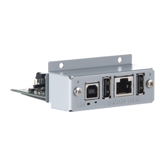
■ IFBD-HI01X
DIP Switch
1
ON
2
Screws
SW
100/10 B ASE
Push Switch
LED
Setting the DIP Switches : Ethernet
The timeout time when acquiring the address from the DHCP/BOOTP server can be set using
DIP switch No. 1. If DIP switch No. 1 is set to ON, a timeout is not performed. If the address can-
not be acquired due to the timeout, set DIP switch No. 1 to ON.
DIP Switch No.
Description
1
Timeout Time
2
TFTP Client
Initializing Ethernet Settings
Set the push switches as described below to initialize the setting information. Push the switch-
es for 5 to 9 seconds while running under normal operating mode. The LED will flash with a red
regular pattern.
After that, push the switches once again in that state to turn OFF the LED. This will return the
settings of the interface board to their factory default settings. After the interface board has
been initialized, the printer will automatically reboot itself.
© Copyright 2015-2016 Star Micronics Co., Ltd.
■ IFBD-HI02X
DIP Switch
1
2
S W
1 0 0 / 1 0 B A S E
Push Switch
LED
ON
OFF
None
20 Seconds *
Valid
Invalid *
* : factory default setting
Connecting to the Host Device (PC)
Ethernet Cable
◆
Note that the Ethernet cable is not provided. Please use a cable that meets specifications.
(1) Make sure the printer is turned off.
(2) Connect the Ethernet cable to the connector on the interface
board. Then, connect the other end of the cable to the hub or
the router.
(3) You can check the MAC address, the settings of the interface
board and the IP address by running a self-print.
USB Cable
◆
Note that the USB cable is not provided. Please use a cable that meets specifications.
(1) Make sure the printer is turned off.
(2) Connect the USB cable to the USB port (USB type B) of the
printer.
ON
Note: When the USB cable is connected to this product, it protrudes
from the back face of the printer.
You cannot place the printer so as to closely fit the wall or
install the printer vertically.
Printer Driver / Utility Software
The printer driver and utility software can be downloaded from the following site.
Screws
http://www.star-m.jp/prjump/000034.html
Printer Firmware
Not all versions of the printer firmware can be used with the IFBD-HI01X/IFBD-HI02X. For de-
tails, refer to the following site.
http://www.star-m.jp/prjump/000045.html
Connecting the USB device
You can use the USB device (such like the USB dongle for wireless communication and the bar-
code reader) which is supported by this product, by connecting it to the USB port (USB type A).
For information related to the USB devices supported by this product, please visit the following
website.
http://www.star-m.jp/prjump/000046.html
USB dongle
Barcode reader
Advertisement
Table of Contents

Related Manuals for Star IFBD-HI01X


Summary of Contents for Star IFBD-HI01X
- Page 1 Push Switch Setting the DIP Switches : Ethernet Not all versions of the printer firmware can be used with the IFBD-HI01X/IFBD-HI02X. For de- tails, refer to the following site. The timeout time when acquiring the address from the DHCP/BOOTP server can be set using http://www.star-m.jp/prjump/000045.html...
- Page 2 20 秒 * 本製品の対応する USB デバイスについては下記の WEB サイトでご確認ください。 TFTP クライアント 有効 無効 * http://www.star-m.jp/prjump/000048.html * : 工場出荷時設定 イーサネット設定の初期化 設定情報を初期化する場合は、プッシュスイッチを以下のようにしてください。 通常動作状態にて、プッシュスイッチを 5 秒~ 9 秒の間押してください。LED が規則的な赤点滅状態とな ります。 この状態からさらにもう一度短くプッシュスイッチを押すと、 LED が消灯状態となり、 インターフェ USB ドングル イスボードの設定が工場出荷時の設定に戻ります。インターフェイスボードの初期化が終了した後、自動 的にプリンターにリブートがかかります。 バーコードリーダー © Copyright 2015-2016 Star Micronics Co., Ltd.
Need help?
Do you have a question about the IFBD-HI01X and is the answer not in the manual?
Questions and answers