Table of Contents
Advertisement
Advertisement
Table of Contents

Related Manuals for B&B F 5

Summary of Contents for B&B F 5
- Page 1 TECHNICAL DESCRIPTION Radio control for forestry cable winches 1st Edition...
-
Page 2: Table Of Contents
Contents General ..........................4 Scope of delivery and use as intended...................5 1.1.1 Scope of delivery ..........................5 1.1.2 Use as intended ..........................5 Saftey notes ............................6 Receiver F5 E ........................7 Installing the F5 E receiver .........................7 Connection of the F5 E receiver and wiring diagram of the load outputs ......8 2.2.1 Option: "Aerial socket F5 E/F9 E"... - Page 3 Note All technical specifications and details in this description have been conceived with the greatest care. Neverthe- less, errors can not be entirely excluded. We would therefore like to mention that we cannot accept any legal responsibility or liability for any consequences resulting from incorrect details/specifications. Due to the ongoing development, the construction and wiring, your device may differ from the specifications contained in this description.
-
Page 4: General
General The radio control F5 is the entry-level model for the professional range of forestry radio controls. An inexpensive control which nonetheless satisfyies the professional requirements for working in the forest: Protection class IP 65, Solid rubber-protected aluminium housing, Safe operation even in an extremely ... -
Page 5: Scope Of Delivery And Use As Intended
Scope of delivery and use as intended 1.1.1 Scope of delivery Transmitter F5 S with protection cap for charging jack Receiver F5 E with connection cable and plug for the winch Mains charger LG5/9 Technical description F5 ... -
Page 6: Saftey Notes
Saftey notes Before operating the radio control equipment, first read the technical description in its entirety and ensure it is always kept available in a suitable protective cover for use on site. The receiver may only be installed by a qualified electrician acording to the pin assignment dra- ... -
Page 7: Receiver F5 E
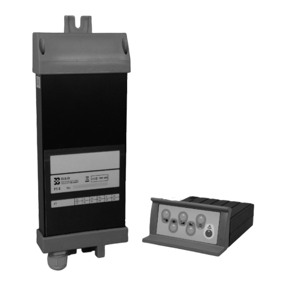
Receiver F5 E Installing the F5 E receiver Mount the receiver inside of the driver's cabin using the two swivel metal brackets vertically with the cable pointing downwards. To achieve good reception, the beveled plastic top, where the integrated aerial is located, should be mounted as close as possible to the edge of the window in the driver's cabin. -
Page 8: Connection Of The F5 E Receiver And Wiring Diagram Of The Load Outputs
Connection of the F5 E receiver and wiring diagram of the load outputs The connection box for the winch may only be connected up by a qualified electrician according to the valid pin assignment drawing. The F5 E receiver may only be connected to the 12 V onboard power supply and has no operating switches of its own. -
Page 9: Startup
Startup Before connecting the receiver, check that the speci- fications on the type plate (see table below) match those of your skidder. Likewise, the device codes in the serial numbers of the receiver and transmitter must also be the same. Key to the specifications and operating modes on the receiver label: The relevant operating mode for the type concerned is marked by a point (l) in the corresponding field. -
Page 10: Function Check
2.3.1 Function check Warning! Risk of accident due to other winch controls. If there are two separate connectors for the manual control and the radio remote control on your skid- der, only one control system may be connected at any one time! Thus ensure that the manual control cable is disconnected first before starting to operate the remote control system. -
Page 11: Fault-Free Operation
2.3.2 Fault-free operation A precondition for a trouble-free operation are electrically perfect connections throughout the entire wiring system. In this regard please follow the instructions on Maintenance given in Chapter 4. In contrast to to a portable control unit, besides the positive supply voltage the wireless receiver also needs an low-resistant ground or 0 Volt connection. -
Page 12: Parameterisation
Parameterisation 2.4.1 Single Function "SF" (EF) / Dual Function "DF" (DF) Single Function EF Single function or SF stands for the operating mode in which, when the Pull command is given, the brake is automatically released simultaneously by a special mechanism in the winch. Dual Function DF Dual function or DF stands for the operating mode in which, when the Pull command is given by the receiver, the Release command is send at the same time to the winch, because the winch doesn’t have an automatic release. -
Page 13: Simple Speed Control (Ge) / Continuous Speed Control (Gs)
2.4.2 Simple Speed Control (GE) / Continuous Speed Control (GS) The factory set operating mode is used to switch on and off the higher rotational speed, or the continuous control of the motor speed. In "GE" mode in conjunction with a solenoid or a pneumatic or hydraulic cylinder at the Bowden ... -
Page 14: Layout Of Load Relays And Fuses
Layout of load relays and fuses Caution! Damage due to incorrect handling. The receiver may only be opened by trained and authorised electrical staff! Pull out the connection cable before opening the receiver. Warning! Fire hazard: Never short-circuit fuse! Load relay Relay Description Emergency... -
Page 15: Changing Fuses
2.5.1 Changing fuses The work on the open receiver described below may only be carried out by qualified staff! Before pulling out the board, ensure that the surroundings where it is to be put down are clean, dry and free of dust. -
Page 16: Transmitter F5 S
Transmitter F5 S Carrying the transmitter For preference carried on the hip wearing a belt. In front of the chest using a shoulder strap*. Attaching the shoulder strap First insert the fastening hooks of the belt into the small holes in the folds of the buckle on the back of the trans- mitter and then close them up. -
Page 17: Gas On / Gas Off (Gas + / Gas -)
3.2.2 Gas ON / Gas OFF (Gas + / Gas -) In the "Simple Speed Control" version (GE), the output "Gas+" is switched on with the "Gas+" button and swit- ched off again with the "Gas-" button. In the "Continuous Speed Control" version (GS), a stroke spindle motor connected to the "G+" and "G-" outputs (not included in the delivery) increases the motor speed for as long as the "G+"... -
Page 18: Recharging The Transmitter Battery
Recharging the transmitter battery When the control lamp on the transmitter blinks briefly three times at short intervals, this indicates that the battery charge is low and it must be recharged. However, if you fail to notice the control lamp, there is no risk of damage due to the battery running down, as the transmitter will switch itself off automatically after a short time. -
Page 19: Charging The Battery From A Vehicle's 12 V Socket (In Preparation)
3.3.2 Charging the battery from a vehicle's 12 V socket (in preparation) To avoid any risk damage to your equipment, only use the 12 V charging adapter approved by TELENOT. Pull the protection cap off the charging jack. Plug the cable socket connector of the 12 V charging adapter (optional) onto the charging jack on ... -
Page 20: Maintenance
Maintenance The F5 is maintenance free. However - observing the following advice may increase your personal safty and the economic life-time of the components. Ensure that the protection cap of the charging jack on the transmitter is always in place when ... -
Page 21: Option: "Emergency Call Via Mobile Emergency System Comtac 1204
Option: "Emergency call via mobile emergency system comtac 1204" Using the mobile emergency call system comtac 1204 it is not only possible to raise the alarm locally through an acoustic signal but also to send out an additional emergency call via the GSM wireless network to an emergency call centre manned 24 hours a day. -
Page 22: Technical Data
Technical Data Frequency range 70 cm-ISM-band, 6 factory-settable radio channels Channel 1: 434,100 MHz Channel 2: 434,250 MHz Channel 3: 434,400 MHz Channel 4: 434,475 MHz Channel 5: 434,550 MHz Channel 6: 434,700 MHz Device code 5-digit (unique code) Control commands 4, plus 1 emergency command Modulation Hamming distance... - Page 23 These signs confirm conformity of the device to the EMV Guideline 2004/108/EC, the Low Voltage Guideline 2006/95/EC and the R&TTE Guideline 1999/5/EC. The F5 radio control device can be operated using the specified operating frequencies in numerous EU countries sowie iin "CH" und "FL" without any restrictions EC Declaraction of conformity and delivery note You can download a Declaration of Conformity and a Delivery Note form for repairs from www.funk-im-forst.de...
- Page 24 Subject to technical changes...
Need help?
Do you have a question about the F 5 and is the answer not in the manual?
Questions and answers