
Related Manuals for B&B F10

Summary of Contents for B&B F10
- Page 1 WIRELESS CONTROL FOR FORESTRY CABLE WINCHES F10 ET F10 DT OPERATING INSTRUCTIONS Version (06) english...
- Page 2 TELENOT ELECTRONIC GMBH B & B Product Division Wiesentalstraße 42 73434 AALEN GERMANY Tel. +49 7361 946-4813 Fax +49 7361 946-440 E-Mail: service@forest-frequency.com Internet: http://www.forest-frequency.com Translation of the German original operating instructions...
- Page 3 These operating instructions enable the safe and efficient use of wireless control into operation, and store the operating instruc- the wireless control for F10 forestry cable winches. tions in a suitable protective cover at the location of use so they All stated safety notices and instructions must be observed to can be easily accessed.
- Page 4 User notes Limitation of liability General Conditions of Sale All technical information in this description has been created You can find the General Conditions of Sale at our website at with the utmost care. Nevertheless, errors cannot be totally http://www.funk-im-forst.de. excluded.
- Page 5 Receiver rating plate Fax +49 7361 946-440 E-Mail: service@forest-frequency.com TELENOT ELECTRONIC GMBH Internet: http://www.forest-frequency.com Wiesentalstraße 42 73434 Aalen DEUTSCHLAND 000000000000031 Serial number F10 S Funksende r 434 MHz Band Transmitter rating plate Baujahr 2014 Serial number 000000000000031 F10 wireless control specification plate...
- Page 6 User notes Explanation of symbols Requirements for safe operation Symbols indicate safety guidelines and warning notices. The symbol is accompanied by a signal word that conveys the extent NOISE! of the danger. Hearing damage due to noise! It is essential to observe these notices to avoid accidents, perso- nal injury, and damage to property! Tips and recommendations for correct operation DANGER!
-
Page 7: Table Of Contents
8.1.1 F10 ET ......22 Special risks ......11 8.1.2... -
Page 8: Table Of Content
Carrying on the body ....35 17.2 F10 E receiver ......52 11.1.2 Mounting with bracket for transmitter . -
Page 9: Safety Notes
Safety notes Safety notes People carrying medical devices should check the com- patibility of their devices with the wireless control that is The operating instructions provide important information for constructed according to EN 62479. handling the device. All stated safety notices and instructions must be observed to ensure safe working. - Page 10 Safety notes DANGER! Requirements for safe operation Danger from unintentional triggering of functions or starting up Wear protective work clothing suitable for the activity and Ensure that no unintended actuation of the transmitter the deployment location (PPA). can be caused by items of clothing and similar items. Before switching on the wireless control, ensure that nobody Switch the transmitter off during break times and at the could be put at risk from operation.
-
Page 11: Special Risks
Safety notes Special risks 3 3 3 Short circuit WARNING! 3 3 1 Defective control elements Fire hazard from short circuits! CAUTION! In the event of a short circuit, very high currents may Residual risk! occur which could, for example, heat up plug connec- Even if the operator follows the procedures correclty, a tions and cables considerably. -
Page 12: Handling Packaging Materials
Safety notes Storage and handling the transmitter battery 3 4 2 Handling packaging materials (eneloop®) Packaging materials are valuable raw materials which can often be re-used or recycled. Batteries gradually lose capacity with age and operating times become shorter. Dispose of the packaging materials in an environmentally Only recharge the battery when it is empty. -
Page 13: Conduct In The Event Of Danger And Accidents
Safety notes Conduct in the event of danger and accidents CAUTION! Eye injuries or property damage can occur if the batte- Preventive measures ries are not handled properly! You must always be prepared for the case of accidents or Only charge the rechargeable batteries in charging devices fire. -
Page 14: Delivery
- 230 V battery charger A-LG 230 V - Accessories kit with 4 NiMH eneloop® AA batteries in a plastic box, waist belt and chest carrying belt, 3 metal vibration dampers for F10 E receiver and B&B pen - F10 original operating instructions... -
Page 15: System Overview
System overview System overview The F10 wireless control is used for the wireless control of cable Transmitter Transmitter F10 S (ET) F10 S (DT) winches. Depending on the model, single (ET) and double-drum winches (DT) of all makes can be controlled. -
Page 16: Function Overview
Function overview Function overview Transmitter The F10 wireless control was specially designed for the harsh requirements of the forest. Sophisticated radio electronics in a robust housing makes the F10 the optimum device for professional log-moving work. The wireless control is suitable both for use on forestry vehicles with permanently attached cable winches and for 3-point cable winches on agricultural tractors and towing vehicles. -
Page 17: Receiver
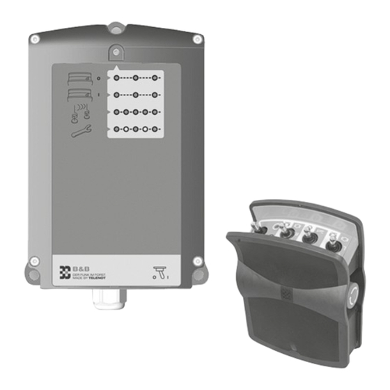
The receiver is switched on and off with a switch. The receiver electronics are contained in a robust polyamide housing and protected against dust and splashing with water (protection to IP65). ON/OFF switch O = OFF I = ON F10 E receiver... -
Page 18: Device Features Device Models
F10 DT wireless control Device models 7 1 1 F10 ET wireless control F10 DT Set F10 DT (ready for connection) for double-drum winches with three additional commands (MAS option) F10 ET Functions Set F10 ET (ready for connection) for single-drum winches with Pull (left/right) -
Page 19: Device Features
Device features Device features 7 2 3 Receiver features Shock-proof housing made from PC/ABS polyamide 7 2 1 General features ON/OFF switch Operationally safe function on the 70-cm ISM band Diagnostics LED Bidirectional wireless technology Protection type IP65 3 working channels Dimensions (W x H x D) 152 x 218 x 51/66 mm Can be individual adjustmented to the special factors Operating voltage +10 V to +30 V DC... -
Page 20: Options
Device features 7 2 4 Options For F10 ET and F10 DT there are different options which you can order with the package and which are pre-installed at the factory: F10 ET device model Option Art -No Note Stutter brake... - Page 21 109536052 Installed at the factory with the emergency call TD comtac 2204-C, housing: W×H×D straight from the factory (152×218×66) mm and the remote antenna option (AA F10): BNC socket for external (Option comtac 2204-C) antenna installed at the factory. The external antenna for attaching (Art. No. 109535858) or for remote mounting (Art.
-
Page 22: Functional Description Structure
Functional Description Functional Description 8 1 2 F10 ET with stutter brake option Structure 8 1 1 F10 ET F10 ET SB transmitter operation options Switch 1 - Operating level 1 (green): Pull drum / release brake F10 ET transmitter operation options - Operating level 2 (gray): Additional command A (e.g. -
Page 23: F10 Dt
Functional Description 8 1 3 F10 DT 8 1 4 F10 receiver F10 DT transmitter operation options Switch 1 - Operating level 1 (green): Pull drum left / release brake left - Operating level 2 (gray): Additional command A (e.g. power take-off shaft ON) / permanent brake... -
Page 24: Functions
Functional Description All outputs except "Emergency" are monitored for Diagnostics LED blink sequence red, orange: - Siren monitoring has triggered functionality or short circuits and indicated by the diag- nostics LED in the event of failure. The "Siren" output is -->... -
Page 25: Release Brake
Functional Description 8 2 2 Release brake Winch type Operation mode The function "Release brake" (release winch brake) is Single function (EF) / Duration of perma- started by holding the switch in the direction of this dual function (DF) nent brake release icon and is stopped by releasing the switch (jog mode). -
Page 26: Gas Adjustment
Functional Description The function "release brake without permanent brake Application: release" can be parametrized at the factory. The motor speed is controlled, for example, on the throttle rods This function is intended for winches with cable ejec- upwards (Gas +) or downwards (Gas –) by a lifting spindle motor tion in order to prevent accidental permanent brake (e.g. -
Page 27: Active Emergency Call Function ("Active Emergency")
Functional Description 8 2 4 Active emergency call function To trigger "Active emergency", press the stop and emergen- ("Active emergency") cy call switch The active emergency call function is used to summon help if First the pre-alarm (2 s sound, 2 s pause) and after 30 s the the person involved in an accident is still capable of triggering main alarm (1 s sound, 1 s pause) through the siren;... -
Page 28: Passive Emergency Call Function ("Passive Emergency")
Functional Description 8 2 5 Passive emergency call function Passive emergency ("Passive emergency") criterion Siren The passive emergency call function is used to summon help if the person involved in an accident is no longer capable of 180 s 120 s triggering an active emergency call. -
Page 29: Motor Start" / "Motor Stop" (Optional)
Functional Description Within the passive emergency period (180 s) and during The option "Motor start" / "Motor STOP" in the F10 ET the pre-alarm, the next sequence can be stopped by with- model contains the additional command A (e.g. for drawing the passive emergency criterion or by actuation. -
Page 30: Stutter Brake (Optional)
The "Anti-tipping function" option can only be ordered and closed time (CT) of the brake changes periodically. The for F10 ET single-drum wireless controls and must be longer the closed time is in comparison to the open time, the installed at the factory. -
Page 31: Remote Antenna Aa F10 (Optional)
Functional Description 8 2 9 Remote antenna AA F10 (optional) Attach the antenna to a protected space on the vehicle's rear side to prevent damage. When doing so, no metallic The "Remote antenna" option must be installed at the parts (with the exception of installation surfaces) factory. -
Page 32: Changing The Wireless Channel
If there are faults due to wireless controls being operated in parallel, the wireless channel can be changed (factory setting: channel 2). The F10 wireless control works on the 70-cm ISM band and can be operated on 3 wireless channels: Channel 1: 434.175 MHz Channel 2: 434.475 MHz... -
Page 33: Accessories
Carrying strap can only be used together with the waist belt. Bracket for transmitter 109536084 Bracket for the F10 S transmitter for mounting in a tractor or as a wall bracket in a garage, for example. Material steel plate, smooth matte WARNER M-Track 1 gas... -
Page 34: 10 Mechanical Structure
Diagnostics LED Battery compartment screw cap ON/OFF switch The transmitter of the F10 remote control consists of a plastic The receiver of the F10 remote control consists of a two-part housing (polyamide 66-GF+TPE) with protection class IP65. Vie- plastic housing (PC / ABS) with protection class IP65. 3 moun- wed from the perspective of the user, the belt plate for feeding ting clips are provided for mounting. -
Page 35: 11 Mounting
Carrying the transmitter on your hip The transmitter of the F10 wireless control can be worn on the hip using the waist belt contained in the package. To do this the waist belt must be attached to the transmitter:... -
Page 36: Mounting With Bracket For Transmitter
Mark the fixing holes using the dimensional sketch. Drill appropriate holes for the screws used. The transmitter of the F10 wireless control can be attached to the wall or to the vehicle using the bracket for the HG1 trans- Depending on the surface, use for example sheet metal mitter. -
Page 37: F10 E Receiver
Mounting 11 2 F10 E receiver 11 2 1 Mounting location requirements The receiver must be tightly bolted to the vehicle! To achieve the broadest range possible, the ideal mounting location is at the rear of the vehicle. Avoid mounting in completely closed metal housings to ensure the unhindered emission of the antenna. -
Page 38: F10 E Receiver Installation
Mounting 11 2 2 F10 E receiver installation Mark the fixing holes using the dimensional sketch. Mount the receiver vertically with the cable gland Drill appropriate holes for the screws used. downwards. The antenna must be as far away from metal... -
Page 39: 12 Connections And Interfaces
Socket 3 (BU3): USB socket Socket 4 (BU4): 8-pole terminal block for anti-tipping system and CAN BUS Plug 2 (ST2): 16-pole plug frame for connecting a ribbon cable for the emergency call TD (parallel S1 interface) Position of F10 E connections... -
Page 40: Connection Configuration
Optional EMERGENCY potential-free Output Motor STOP Output Additional command B Output Siren (pre-alarm, main alarm) Output Release brake right (only for F10 DT) Output Pull drum right (only for F10 DT) Output Pull drum (for F10 DT left) Table: Socket 1 connection configuration... -
Page 41: Socket 2
Connections and Interfaces 12 3 2 Socket 2 Socket 2 connection configuration Type Labeling / icon Function Technical Data Output Release brake (for F10 DT left) Switches +U / max. 5 A Output Motor start Output Gas + Output Gas – Output Additional command A... -
Page 42: Socket 4
Connections and Interfaces 12 3 4 Plug 2 12 3 3 Socket 4 Type Function Technical Data Power for emergency / max. Socket 4 connection configuration call TD 300 mA Pin Type Labeling / icon Function Technical Data Power GND for emergency call TD CANH Vacant... -
Page 43: 13 Installation
13 Installation DANGER! Danger due to malfunctions as a result of incorrect The F10 wireless control connection cable is already prewired at cabling the factory to one or several plugs (e.g. 7-pole vehicle connector). The receiver may only be connected by a specialist accor- The assignment and plug type depend on the winch type. -
Page 44: 14 Wiring Diagrams
Pull drum left (ET) lay contacts from sticking, Solenoid valves Release brake left (ET) inductive consumers must be provided with a flyback Pull drum right (DT diode (e.g. 1N4007). Release brake right (DT) Outputs for special purposes F10 E receiver wiring plan... -
Page 45: 15 Parameterization
Parameterization 15 Parameterization Application: Controlled lowering of loads 15 1 Who performs the parameterization? Description: Nearly all functions are already parametrized at the factory. The winch brake is opened and closed automatically at short, Additional options are also parametrized at the factory. parameterizable time intervals. -
Page 46: Brake Open Time (Ot) Parameterization
Parameterization 15 2 1 Brake open time (OT) parameterization To reduce the open time, press the switch "Stutter brake" towards the body and hold the switch in this position. Also First set the open time of the brake (OT). It determines the speed briefly touch the switch for "Gas +". -
Page 47: Brake Closed Time (Ct) Parameterization
Parameterization 15 2 2 Brake closed time (CT) parameterization To reduce the closed time, press the switch "Stutter brake" away from the body and hold the switch in this position. After the open time, set the closed time of the brake (CT). It Also briefly touch the switch for "Gas +". -
Page 48: 16 Commissioning
Commissioning 16 Commissioning 16 2 2 Transmitter battery installation Groove for guide tab 16 1 Requirements The correct cabling of the receiver to the winch or to the vehicle has been performed by a specialist according to the relevant pin assignment diagram. Groove for guide tab The transmitter battery is charged. -
Page 49: Functional Test
Operating level LED clockwise direction and first switch the transmitter off with the ON/OFF switch and then back on again. F10 S transmitter activation The siren is muted and the "Emergency" output switches itself off again (only with main alarm). Press the stop and emergency call switch. -
Page 50: Fault-Free Operation
Commissioning When using the function "Passive emergency call", Check whether the diagnostics LED on the receiver check whether this function works: Place the trans- begins to flicker or goes off in an operating state. In this mitter on the ground and wait until the pre-alarm is instance there is a poor contact in the supply voltage of the receiver. -
Page 51: 17 Operation
Operation 17 Operation DANGER! Danger from unintentional triggering of functions or 17 1 Safety notices for operation starting up Ensure that no unintended actuation of the transmitter DANGER! can be caused by items of clothing and similar items. Danger from vehicles tipping over Switch the transmitter off during break times and at the Ensure that the vehicle has the necessary stability. -
Page 52: F10 E Receiver
Wear protective work clothing suitable for the activity and the deployment location (PPA). 17 2 F10 E receiver Before switching on the wireless control, ensure that nobo- dy could be put at risk from operation. Always work with a direct line of sight to the machine and... -
Page 53: F10 S Transmitter
Operation 17 3 F10 S transmitter 17 3 1 F10 S transmitter LED displays Switch the transmitter on with the ON/OFF switch (tilt to ON/OFF switch the right). Status LED The diagnostics LED on the receiver blinks green. Operating level LED The status LED on the transmitter flashes green (when battery charged). -
Page 54: Release Brake
ON/OFF Flashes red No wireless response received by receiver (e.g. beyond range) Table: F10 S transmitter indications; operating level LEDs Status LED Operating level LED Release brake command Press the switch briefly (< 1.5 s). The brake opens for the duration the switch is pressed and immediately closes again when it is released (jog mode). -
Page 55: Permanent Brake Release
Operation 17 3 3 "Permanent brake release" Operating level 2 (gray background) Operating level 1 (green background) Via function "Release brake" Status LED Operating level LED Status LED Permanent brake release command through operating level 2 (2-switch operation) Operating level LED Release brake command Press the ON/OFF switch towards "ON"... -
Page 56: Pull Drum
Operation 17 3 4 Pull drum DANGER! Danger from vehicles tipping over Ensure that the vehicle has the necessary stability. Check the subsoil. Recommendation: the anti-tipping system option. Status LED DANGER! Operating level LED Danger from pulling up tree trunks Pull drum command Do not touch the towing cable during operation! Nobody should be located around the intake zone of... -
Page 57: Gas
Operation 17 3 5 Gas + 17 3 6 Gas – Status LED Status LED Operating level LED Operating level LED Gas + command Gas – command Press the switch briefly. An increase in motor speed occurs Press the switch briefly. A reduction in motor speed occurs for the duration of actuation. -
Page 58: Motor Start
Operation 17 3 7 "Motor start" Motor start through Motor STOP (MAS) Press the ON/OFF switch towards "ON" and keep it in this position. Operating level LED lights up green. Press the switch briefly towards the body ("Motor STOP"). The motor stops if it is running. Within 6 s following "Motor STOP", press the switch briefly away from the body;... -
Page 59: Motor Stop
Operation 17 3 8 Motor STOP 17 3 9 "Additional command A" The "Additional command A" option is parametrized with the option "Motor start/STOP" at the factory. Status LED Status LED Operating level LED Operating level LED Motor STOP command Additional command A command Press the ON/OFF switch towards "ON"... -
Page 60: Stutter Brake
Operation 17 3 10 "Stutter brake" The "Stutter brake" switch has the same function in both actuation directions. Details: See function description / functions / stutter brake STOP (optional) WARNING! Parameterization of the function stutter brake: see parameteri- Danger from falling load zation / parameterization stutter brake Ensure that nobody is near the load to be lowered. - Page 61 Operation 17 3 11 Triggering "Active emergency" After a period of time parameterizable at the factory (facto- ry setting: 30 s) the "Emergency" output is activated and the main alarm is tripped (siren: 1 s sound, 1 s pause, etc.). The stop and emergency call switch remains functional even when the transmitter is switched off.
-
Page 62: Reset "Active Emergency
Operation 17 3 12 Reset "Active emergency" Switch the transmitter off by pressing the ON/OFF switch towards "OFF" (O). Switch the transmitter back on by pressing the ON/OFF switch towards "ON" (I). The siren and the "Emergency" (only with main alarm) out- put are switched off and the alarm is reset. -
Page 63: Reset "Passive Emergency
Passive emergency is switched on The transmitter switches Operating level LED itself off again Switch the transmitter on (see operation / F10 S transmitter) if you want to resume your work. Details: See function description / functions / function passive Reset alarm after "Passive emergency"... -
Page 64: Switch Off "Passive Emergency
Passive emergency is deactivated and the transmitter swit- ches itself off again. Switch the transmitter back on (see operation / F10 S transmitter) as soon as you want to resume your work. Details: See function description / functions / function passive emergency call ("passive emergency") -
Page 65: Device Model F10 Dt Wireless Control
Device model F10 DT wireless control with the motor start/STOP option. The option "Stutter brake" is not available for the device model F10 DT. All other functions are to be operated the same way as with the device model F10 ET. -
Page 66: Eliminate Fault States
Operation 17 4 Eliminate fault states Fault Solution Diagnostics LED on the receiver is off Check the reciever and voltage supply Diagnostics LED on the receiver flashes red Switch on transmitter / bring transmitter within the receiver's range Diagnostics LED on the receiver flashes alternately, red / Check fuse 5 and supply cable for the siren orange (siren monitoring has tripped) Diagnostics LED on the receiver flashes alternately, two... -
Page 67: 18 Maintenance And Service
Maintenance and service 18 Maintenance and service If you discover a fault: DANGER! 18 1 Recommended maintenance interval Danger due to malfunctions Carry out maintenance work at least once a year. Do not work with a defective system. Send back the whole system for repair in appropriate packaging with 18 2 Scope of maintenance the transmitter and receiver, including the connection... -
Page 68: Cleaning The Transmitter And Receiver
(see commissioning / preparation / installing the Si 4 Si 3 transmitter batteries). In the event of an emergency, a work process that has begun can be ended by switching on the transmitter again. Position of the fuses and relay in receiver F10 E... - Page 69 Gas – 7.5 A Release brake L, permanent brake release L, Si 5 Siren 7.5 A cable ejection Table: Plug fuses in the F10 E receiver Gas + All fuses: Vehicle mini plug fuse (mini fuse) Gas – Unlock +UB Motor start Additional command A Table: Relays...
-
Page 70: 19 Disassembly And Disposal
Switch off transmitter and remove batteries In general, do not interfere with the device any further, 19 2 F10 E receiver disassembly as this will invalidate the warranty. If available: Disassemble the remote antenna. Remove the 3 fixing screws of the receiver housing. -
Page 71: Disposal
Disassembly and disposal 19 3 Disposal Scrap the metal parts Hand in synthetic elements for recycling Recycle electrical and electronic parts, or return them to TELENOT. The product is subject to the valid EU WEEE Directive (Waste Electrical and Electronic Equipment). As the owner of this product, you are obliged by law to dispose of waste equipment at a recycling plant, separately from the domestic waste. -
Page 72: 20 Technical Data
Technical Data 20 Technical Data Transmitter Feature Figure Feature Figure Range Several hundred meters in a free field Frequency range 70-cm ISM band, 3 wireless channels (434.175 MHz / Power supply 2 eneloop® AA rechargeable batteries 434.475 MHz / 434.675 MHz) 1.2 V DC / 1,900 mAh (optional 2 AA batteries) System address Unique address for transmitter and recei-... - Page 73 (152×218×51) mm, Make sure to obey the country-specific laws and regulations for with emergency call TD (152×218×66) mm use of radio networks. The F10 wireless control may be operated without restriction with the specified operating frequencies Color Black in the following countries: Albania, Andorra, Austria, Belgium,...
-
Page 74: Declaration Of Conformity
Declaration of conformity... - Page 75 Test certificate from the KWF (Kuratorium für Waldarbeit und Forsttechnik e.V.)
- Page 76 Wireless control F10 Radio control F10 Transmitter operation (basic functions) You can find the extended functions in the technical description. Symbol overview Hold in „ON“ Additional Additional Transmitter OFF Motor start Keep "on" position command A command B Transmitter ON Increase motor „ON“...
Need help?
Do you have a question about the F10 and is the answer not in the manual?
Questions and answers