Table of Contents
Advertisement
Available languages
Available languages
Dove non diversamente specificato, i dati e le prescizioni si riferiscono a tutti i modelli.
Unless specified, data and presciption are referred to all t he models.
Sauf indications contraires, les données et les instructions se réfèrent à tous les modèles.
Wo nicht anders ausdrücklich angegeben, beziehen sich die Daten und die Vorschriften auf alle Modelle.
Donde no especificado, los datos y resenas se refieren a todos los modelos.
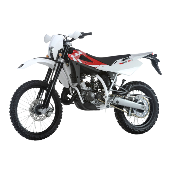
WRE 125
SMS 125
SMS 125
SMS 125
WRE 125 2011
SMS 125 2011
CARATTERISTICHE - USO - MANUTENZIONE
SPECIFICATIONS - OPERATION - MAINTENANCE
CARACTERISTIQUES - UTILISATION - ENTRETIEN
MERKMALE - GEBRAUCH - WARTUNG
CARACTERISTICAS - USO - MANTENIMIENTO
IT - 1
Advertisement
Chapters
Table of Contents

Related Manuals for Husqvarna WRE 125 2011


Summary of Contents for Husqvarna WRE 125 2011
- Page 1 WRE 125 SMS 125 SMS 125 SMS 125 WRE 125 2011 SMS 125 2011 CARATTERISTICHE - USO - MANUTENZIONE SPECIFICATIONS - OPERATION - MAINTENANCE CARACTERISTIQUES - UTILISATION - ENTRETIEN MERKMALE - GEBRAUCH - WARTUNG Dove non diversamente specificato, i dati e le prescizioni si riferiscono a tutti i modelli.
-
Page 2: Table Of Contents
Note SOMMARIO Pag. l Le indicazioni di destra e sinistra si riferiscono ai due lati del motociclo rispetto al senso di marcia. PRESENTAZIONE ............3 AVVERTENZE IMPORTANTI..........3 n° denti DATI PER L’IDENTIFICAZIONE ........5 l Z: UBICAZIONE COMANDI ..........6 l A: Austria DATI TECNICI ...............7 AUS: Australia TABELLA DI LUBRIFICAZIONE, RIFORNIMENTI ....8... -
Page 3: Presentazione
AVVERTENZE IMPORTANTI WRE 125 Benvenuti nella famiglia motociclistica Husqvarna! La Vostra nuova motocicletta Husqvarna é stata pro- 1) I modelli WRE ed SMS sono motocicli per impiego gettata e costruita per essere la migliore della sua STRADALE, garantiti esenti da difetti e coperti da garanzia categoria. - Page 4 PRECAUZIONI PER I BAMBINI zione eseguendo i tagliandi presso le ATTENZIONE officine autorizzate HUSQVARNA. Parcheggiare il veicolo dove non possa essere Il costo per la sostituzione dei pezzi e facilmente urtato o danneggiato.
-
Page 5: Dati Per L'identificazione
DATI PER L’IDENTIFICAZIONE Il numero di identificazione del motore è stampigliato sulla parte superiore del carter motore, mentre il nume- ro di matricola del motociclo è stampigliato sul tubo di sterzo del telaio. Riferite sempre, annotandolo anche sul presente libretto, il numero stampigliato sul telaio quando ordinate i ricambi o chiedete informazioni sul vostro motociclo. -
Page 6: Ubicazione Comandi
UBICAZIONE COMANDI 1. Leva comando freno anteriore 2. Manopola comando gas Pulsante ENGINE STOP (arresto di emer- genza del motore) 4. Commutatore sinistro 5. Leva comando frizione 6. Dispositivo starter 7. Rubinetto carburante 8. Pedale comando cambio 9. Pedale comando freno posteriore 10. -
Page 7: Dati Tecnici
DATI TECNICI TRASMISSIONE PRIMARIA (SMS) Pignone motore ......Z 22 in 1a velocità ......30,839 MOTORE Corona frizione . -
Page 8: Tabella Di Lubrificazione, Rifornimenti
PNEUMATICI Peso in ordine di marcia, senza carburante Anteriore (WRE) ....... . kg 108 (SMS) . -
Page 9: Comandi
COMANDI CARBURANTE CAVALLETTO LATERALE Il motociclo monta un motore a due tempi che richiede Ogni motociclo è fornito di un cavalletto laterale (1). RUBINETTO CARBURANTE un’alimentazione di miscela benzina-olio. Il carburante ATTENZIONE*: Il cavalletto è progettato Il rubinetto (1) posto sulla sinistra del serbatoio consta consigliato è... - Page 10 STRUMENTO DIGITALE, SPIE AVVIAMENTO A FREDDO - Il passaggio da una funzione all’altra ed il relativo azzeramento, deve essere effettuato mediante il ta- Il motociclo è equipaggiato con uno strumento digi- Per l’avviamento a freddo il motociclo è provvisto di una sto SCROLL (A).
- Page 11 2- SPEED / CLOCK (figura 2) 3- SPEED / TRIP 1 (figura 3) 1- SPEED (Km/h o mph) / ODO (figura 1) - SPEED: velocità- Indicazione max: 299 Km/h o 299 - SPEED: velocità- Indicazione max: 299 Km/h o 299 - SPEED: velocità...
- Page 12 4- SPEED / CRONOMETRO (STP) (figura 4) 5- SPEED / CONTAORE (figura 5) 6- DIAGNOSTICA CRUSCOTTO (figura 6) - SPEED: velocità- Indicazione max: 299 Km/h o 299 - Conta le ore di funzionamento del motore con cadenza - Il cruscotto è predisposto per indicare eventuali malfun- mph;...
- Page 13 COMANDO GAS COMANDO FRENO ANTERIORE INTERRUTTORE DI ACCENSIONE La manopola (1) del gas è situata sul lato destro del La leva (2) del freno è situata sul lato destro del manu- L’interruttore di accensione consta di due posizioni. manubrio. La posizione del comando sul manubrio può brio.
- Page 14 BLOCCASTERZO COMMUTATORE DESTRO SUL MANUBRIO COMMUTATORE SINISTRO SUL MANUBRIO Il motociclo è fornito di un bloccasterzo (1) posto sul Il commutatore sinistro ha i seguenti comandi: Il commutatore destro ha i seguenti comandi: lato destro del cannotto di sterzo. Flash abbagliante (ritorno automatico) 1) Interruttore di EMERGENZA arresto motore.
- Page 15 COMANDO FRIZIONE COMANDO FRENO POSTERIORE COMANDO CAMBIO La leva (1) è posta sul lato sinistro del motore. Il pilota, La leva (1) della frizione è situata sul lato sinistro del Il pedale (1) di comando del freno posteriore si trova sul ad ogni cambio di velocità, deve lasciare libero il pedale manubrio ed è...
-
Page 16: Istruzioni Per L'uso Del Motociclo
ISTRUZIONI PER L’USO DEL MOTOCICLO ISTRUZIONI PER IL RODAGGIO CONTROLLI DURANTE IL RODAGGIO Le verifiche da effettuare durante il rodaggio sono le NOTA*: Se non avete confidenza col L’esclusività del progetto, l’elevata qualità dei materiali seguenti: funzionamento del motociclo, prima di impiegati e l’accuratezza del montaggio, Vi garantisco- - CONTROLLO TENSIONE RAGGI RUOTE;... - Page 17 INDIVIDUAZIONE DEGLI INCONVENIENTI DI FUNZIONA- Il motore é carente di potenza MENTO - Filtro aria sporco: pulire - Eccessiva distanza elettrodi candela: regolare Il seguente elenco di eventuali inconvenienti di funziona- - Compressione insufficiente: verificarne la causa mento serve, in linea generale, per individuarne l’origine ed attuarne il rimedio.
- Page 18 NOTA AVVIAMENTO DEL MOTORE IMPORTANTE IN CASO DI AVVIAMENTO A ATTENZIONE*: Non avviare mai il moto- FREDDO A BASSE TEMPERATURE re se manca l’olio nel serbatoio (A). Si raccomanda di effettuare un breve riscaldamento al minimo fino a quando, dopo aver disinserito lo starter, ci Per procedere correttamente all’avviamento a freddo del sarà...
- Page 19 IMPORTANTE Non accelerare mai il motore dopo un avviamento a freddo. ATTENZIONE*: I fumi di scarico contengono gas di monossido di carbonio. Non far mai girare il motore in luoghi chiusi. ATTENZIONE*: In fase di avviamento di questo tipo di motociclo ad alte presta- zioni si può...
- Page 20 ARRESTO DEL MOTOCICLO E DEL MOTORE - Chiudere completamente la manopola (1) del gas in modo da far decelerare il motociclo. - Frenare sia anteriormente (2) che posteriormente (3) mentre si scalano le marce (per una forte dece- lerazione, agire in modo deciso sul leva e pedale dei freni).
- Page 21 ARRESTO DEL MOTORE IN EMERGENZA CONTROLLO LIVELLO OLIO TRASMISSIONE/CAMBIO LIVELLO OLIO LUBRIFICAZIONE MOTORE - Premere il pulsante rosso (8) per arrestare il moto- Tenendo il motociclo in piano ed in posizione verticale, Rimuovere la sella ruotando in senso antiorario il perno controllare il livello dell’olio per mezzo dell’oblò...
- Page 22 LIVELLO LIQUIDO DI RAFFREDDAMENTO SOSTITUZIONE OLIO TRASMISSIONE/CAMBIO Controllare il livello (1) nel radiatore destro a motore fred- Rimuovere il paramotore (1) svitando le viti (2). do e con il motociclo in posizione verticale. Il refrigerante Per sostituire completamente l’olio, svitare il tappo (3) deve trovarsi 10 mm (0.39 in) sopra gli elementi.
- Page 23 REGOLAZIONE CAVO COMANDO GAS REGISTRAZIONE MINIMO - se la lunghezza del registro (3) non fosse sufficiente a ottenere la corretta regolazione, agire sul registro posi- La regolazione del cavo comando gas si può effettuare La registrazione del minimo deve essere effettuata solo zionato sul carburatore.
- Page 24 CONTROLLO CANDELA Esatto grado termico: La punta dell’isolante è secca ed il colore è marrone La distanza fra gli elettrodi della candela (2) deve essere chiaro o grigio. 0,6 mm (0.0236 in.). Grado termico elevato: Una distanza maggiore può causare difficoltà di avvia- La punta dell’isolante è...
- Page 25 CONTROLLO FILTRO ARIA PULIZIA FILTRO ARIA - Rimuovere la sella ruotando in senso antiorario il per- Lavare il filtro con un detergente specifico (CASTROL no posteriore (1). FOAM AIR FILTER CLEANER o prodotto similare) ed asciu- - Staccare i cavi (2) e (3) della batteria (4) e rimuover- garlo perfettamente (lavare il filtro con benzina solo in caso di necessità).
- Page 26 Concessionario Husqvarna. AVVERTENZA*: Non versare fluido freni su superfici verniciate o lenti (es. di fa- nali) IT - 26...
- Page 27 REGISTRAZIONE POSIZIONE PEDALE FRENO POSTERIORE La posizione del pedale di comando del freno posteriore rispetto all’appoggiapiede, può essere regolata a secon- da delle esigenze personali. Dovendo procedere a tale registrazione operare nel modo seguente: - allentare la vite (1); - ruotare la camma (2) per abbassare o alzare della di- mensione (A) desiderata del pedale del freno (3);...
- Page 28 Concessio- zionato sulla leva. nario Husqvarna. - Rimuovere la protezione in gomma (1). - Agire sul tenditore (2) sbloccando la controghiera AVVERTENZA*: Non versare fluido freni (3).
- Page 29 SOSPENSIONI REGISTRAZIONE AMMOR TIZZATORE REGISTRAZIONE PRECARICO MOLLA AMMORTIZZATORE La taratura delle sospensioni è stata scelta dopo aver ef- La taratura dell’ammortizzatore è definita per la marcia Per effettuare l’operazione procedere nel modo seguen- fettuato numerose e severe prove nelle varie condizioni con il solo pilota più...
- Page 30 Controllare che la catena abbia una freccia (A) di 12 mm REGISTRAZIONE CATENA (0.47 in.) circa come indicato nella targhetta (1) appo- La catena deve essere controllata, registrata e lubrificata sta sul carter catena. in accordo con la “Tabella di manutenzione”; questo per Se così...
- Page 31 AVVERTENZA*: Controllare l’allinea- LUBRIFICAZIONE CATENA mento del guidacatena. Nel caso si fos- Lubrificare la catena attenendosi alle istruzioni che se- se piegato, potrebbe interferire con la guono. catena provocandone la rapida usura. Si potrebbe inoltre verificare uno scarruco- AVVERTENZA* : Non usare mai grasso lamento della catena dal pignone.
- Page 32 Nota *: SMONTAGGIO RUOTA ANTERIORE RIMONTAGGIO RUOTA ANTERIORE Dopo aver rimontato la ruota, agire sulla leva di coman- Montare il distanziale (D) sinistro sul mozzo ruota. Posizionare un blocco o un cavalletto sotto il motore in do freno fino a portare le pastiglie a contatto del disco. Inserire la ruota tra gli steli della forcella facendo in modo che la ruota anteriore sia sollevata dal terreno.
- Page 33 Nota *: SMONTAGGIO RUOTA POSTERIORE PNEUMATICI Con la ruota smontata, non agire sul pedale del freno per Posizionare un blocco o un cavalletto sotto il motore in Abbiate cura di tenere i pneumatici gonfiati sempre alla non provocare l’avanzamento dei pistoncini della pinza. modo che la ruota posteriore sia sollevata dal terreno.
- Page 34 FRENI CONTROLLO IMPIANTO FRENANTE Controllare periodicamete l'impianto frenante secondo le I principali componenti dei due impianti sono: la pompa scadenze indicate sulla “Scheda di manutenzione perio- freno con relativa leva (anteriormente) o pedale (poste- dica”. riormente), la tubazione, la pinza ed il disco. ATTENZIONE *: LEGENDA Controllare periodicamente le tubazioni di...
- Page 35 USURA PASTIGLIE SMONTAGGIO PASTIGLIE FRENO PULIZIA PASTIGLIE Controllare l’usura delle pastiglie. - Rimuovere le mollette 1. Accertarsi che non ci siano tracce di fluido freni o di olio Il limite di servizio”A” é: 3,8 mm (0.15 in.). - Sfilare i perni 2. sulle pastiglie o sui dischi.
-
Page 36: Ubicazione Componenti Elettrici
UBICAZIONE COMPONENTI ELETTRICI L’impianto di accensione è composto dai seguenti ele- menti: - Generatore (1) all’interno del coperchio del semicarter sinistro; - Bobina elettronica (2) sotto il serbatoio carburante; - Centralina elettronica (3) sotto la sella; - Regolatore di tensione (5) sul lato sinistro del telaio vicino al canotto di sterzo. - Page 37 IT - 37...
- Page 38 NERO o BLU); inconvenienti all’impianto elettrico, rivolgetevi al Conces- - estrarre la batteria (2) dal proprio alloggiamento. occhi e abiti. sionario HUSQVARNA. Antidoto: Nel caso il veicolo debba rimanere inutilizzato per lunghi Verificare, con l’ausilio di un voltmetro, che la tensione ESTERNAMENTE: - Sciacquare con acqua.
- Page 39 Nota*: SOSTITUZIONE LAMPADINE PROIETTORE La lampada (8) del proiettore anteriore è di tipo aloge- Per accedere alle lampadine del proiettore, occorre pro- no; durante la sostituzione occorre prestare attenzione a cedere nel modo seguente: non toccare con le mani nude la parte in vetro. - Svitare la vite (1) e rimuovere il cupolino (4) completo di faro (7);...
- Page 40 FANALE POSTERIORE SOSTITUZIONE LAMPADA LUCE TARGA Il fanale posteriore (1) è del tipo a LED; in caso di non funzionamento deve essere sostituito. - Svitare la vite (1) e staccare la luce targa (2) dal para- fango; - estrarre il portalampada (3) con la lampadina (4) dal suporto;...
- Page 41 REGISTRAZIONE FANALE ANTERIORE Per controllare se il fanale è orientato nel modo corretto mettere il motociclo, con in pneumatici gonfiati alla giu- sta pressione e con una persona seduta in sella, perfetta- mente perpendicolare con il suo asse longitudinale. Di fronte ad una parete o ad uno schermo, distante da esso 10 m (33 ft), tracciare una linea orizzontale corri- spondente all’altezza del centro del fanale ed una verti- cale in linea con l’asse longitudinale del veicolo.
-
Page 42: Appendice
APPENDICE PULIZIA Per rimettere in attività il motociclo, procedere come segue: INATTIVITA’ PROLUNGATA Premesso che, prima del lavaggio del motociclo, è neces- - Accertarsi che la candela sia serrata . Dovendo lasciare inattivo il motociclo per un certo perio- sario proteggere opportunamente dall’acqua le seguenti - Riempire il serbatoio carburante. - Page 43 Serraggio viti e dadi Controllo / serraggio Comando acceleratore Controllo funzionalità 2a-senza tabelle-2004-OK 28-09-2004 16:42 Pagina 279 Comando acceleratore Verifica/regolazione gioco � Fascette stringitubo Controllo / serraggio � Comando starter Controllo funzionalità Lubrificazione generale � � Trasmissioni e com. fless. Controllo / Regolazione �...
- Page 44 INDICE ALFABETICO Pagina LIVELLO OLIO LUBRIFICAZIONE MOTORE ........21 LUBRIFICAZIONE CATENA............... 31 ARRESTO DEL MOTOCICLO E DEL MOTORE ........20 ARRESTO DEL MOTORE IN EMERGENZA .......... 21 AVVIAMENTO A FREDDO ..............10 MONTAGGIO ................. 26 AVVIAMENTO DEL MOTORE ............18 MONTAGGIO PASTIGLIE ..............
- Page 45 ENGLISH EN - 1...
- Page 46 Note SUMMARY Page l References to the “left” or “right” of the motorcycle are considered from the point of view of a person fac- PRESENTATION ............3 ing forward. IMPORTANT NOTICES............3 IDENTIFICATION DATA ..........5 number of teeth CONTROLS LOCATION ...........6 l Z: TECHNICAL DATA ............7 l A: Austria TABLE FOR LUBRICATION, SUPPLIES ......8...
-
Page 47: Presentation
IMPORTANT NOTICES WRE 125 Welcome to the Husqvarna motorcycling Family! Your new Husqvarna motorcycle is designed and manu- 1) WRE and SMS models are STREET LEGAL motorcy- factured to be the best in its field. The instructions in cles; they are guaranteed exempt from functional defects... - Page 48 Note*: Gives helpful information. Parts Replacement When parts replacement is required, use only Husqvarna ORIGINAL parts. WARNING*: After a crash, inspect the motorcycle carefully. Make sure that the throttle, brake, clutch and all other systems are undamaged.
-
Page 49: Identification Data
IDENTIFICATION DATA The engine identification number is stamped at the top of the crankcase, while vehicle serial number or Vehicle Identification Number is stamped on the steering head tube. Always quote the number stamped on the frame when ordering spare parts or requesting further details about your vehicle and note it on this booklet. -
Page 50: Controls Location
CONTROLS LOCATION 1. Front brake lever 2. Throttle twistgrip ENIGINE STOP button (emergency stop) 4. L.H. switch 5. Clutch control lever 6. Starting device 7. Fuel cock 8. Gear shift pedal 9. Rear brake control pedal 10. Kick start pedal 11. -
Page 51: Technical Data
TECHNICAL DATA PRIMARY DRIVE FINAL RATIOS (SMS) Drive pinion gear ......Z 22 1st gear ......30.839 ENGINE Clutch ring gear . - Page 52 TABLE FOR LUBRICATION, SUPPLIES TYRES Kerb weight, without fuel Front (WRE) ......238.01 lb Engine lubricating oil .
-
Page 53: Controls
CONTROLS FUEL SIDE STAND The motorcycle is equipped with 2 stroke engine that A side stand (1) is supplied with every motorcycle. FUEL COCK requires a gasoline-oil mixture. Recommended fuel: pre- WARNING*: The stand is designed to The cock (1) set on tank left-hand side has three posi- mium grade unleaded fuel (R.O.N. - Page 54 DIGITAL DASHBOARD, WARNING LIGHTS - The functions, which can be selected in this sequence, COLD START are as follows: The motorcycle is fitted with a digital dashboard on For engine cold starting, the motorcycle features a lever (3) on the left-hand side of the handlebar. Pull the lever which 3 warning lights are also available: high beam, 1- SPEED / ODO (figure 1) to open the starting device, vice versa to close it.
- Page 55 1- SPEED (km/h or mph) / ODO (figure 1) 2- SPEED / CLOCK (figure 2) 3- SPEED / TRIP 1 (figure 3) - SPEED: vehicle speed - maximum value: 299 Km/h - SPEED: speed - maximum value: 299 Km/h or 299 - SPEED: speed - maximum value: 299 Km/h or 299 or 299 mph;...
- Page 56 6- INSTRUMENT PANEL DIAGNOSTICS (figure 6) 4- SPEED / LAP TIMER (STP) (figure 4) 5- SPEED / HOUR COUNTER (figure 5) - The instrument panel is capable of indicating malfun- - SPEED: speed - maximum value: 299 Km/h or 299 - It counts the engine running hours in 30-minute inter- ctions.
- Page 57 THROTTLE CONTROL FRONT BRAKE CONTROL IGNITION SWITCH The throttle twistgrip (1) is located on the right-hand side The brake control lever (2) is located on the right-hand The ignition switch has two positions. of the handlebar. The position of the throttle control can side of the handlebar.
- Page 58 STEERING LOCK RIGHT-HAND HANDLEBAR SWITCH L.H. HANDLEBAR SWITCH The motorcycle is equipped with a steering lock (1) on The left-hand handlebar switch contains the following The right-hand switch features the following controls: the R.H. side of the steering head tube. commands: 1) Engine KILL SWITCH.
- Page 59 CLUTCH CONTROL REAR BRAKE CONTROL GEAR SHIFT CONTROL The lever (1) is placed on the left-hand side of the en- The clutch lever (1) is located on the left-hand side of the The rear brake control (1) is placed on the right-hand gine.
-
Page 60: Instructions For Using The Motorcycle
INSTRUCTIONS FOR USING THE MOTORCY- INSTRUCTIONS FOR RUNNING-IN CHECKS WHILE RUNNING IN The exclusivity of the design, coupled to the high quality When running in, the following should be checked out: NOTE*: If you are not familiar with the of the materials used and the accuracy of the assembly, - WHEELS SPOKES TENSION;... - Page 61 TROUBLESHOOTING The engine lacks power - dirty air filter: clean The following list is used for troubleshooting and to find - the spark plug electrode gap is too large: adjust; the necessary remedies. - insufficient compression: check for the cause The engine knocks The engine does not start - excessive carbon deposit on the piston crown, or in the...
- Page 62 NOTE STARTING THE ENGINE IMPORTANT NOTE IN CASE OF COLD START WARNING*: Never start the engine if AT LOW TEMPERATURES there is no oil in the reservoir (A). It is recommended to briefly warm up the engine at idle To correctly start a cold engine proceed as follows: until, after having turned off the starting device, the en- gine response when opening the throttle is normal.
- Page 63 IMPORTANT Never accelerate the engine after a cold start. WARNING*: The exhaust fumes contain carbon monoxide gas. Never run the en- gine in a closed garage or in a confined area. WARNING*: This high performance mo- torcycle can some times «kick back» strongly when you are starting it.
- Page 64 STOPPING THE MOTORCYCLE AND THE ENGINE - Close the throttle (1) completely in order to slow down the motorcycle. - Apply both front (2) and rear (3) brakes while down- shifting (for fast deceleration, press firmly on both brake pedal and lever). - When stopped, pull the clutch lever (4) and shift gear lever (5) into the neutral position - Turn the ignition key (6) to the OFF position (posi-...
- Page 65 STOPPING THE ENGINE IN AN EMERGENCY CHECKING THE OIL LEVEL ENGINE LUBRICATION OIL LEVEL - Press the red button (8) to stop the engine. Keeping the motorbike level and upright, check the oil Remove the saddle, turning the rear pin (1) counterclock- level through the inspection (1) window on the right wise.
- Page 66 CHANGING TRANSMISSION/GEARBOX OIL COOLANT LEVEL Check level (1) in right-hand radiator when engine is cold Remove the engine guard (1) by undoing the screws (place the motorbike fully upright). The coolant should be (2). approximately 10 mm (0.39 in.) above the cells. The radia- To completely replace the oil, unscrew the plug (3) under tor cap (2) features two locking positions: the first one is for the oil sump and let oil come out, then screw the plug...
- Page 67 THROTTLE CABLE ADJUSTMENT - if register (3) should not provide sufficient movement ADJUSTING THE IDLE The throttle cable may be adjusted using the adjuster to allow for correct adjustment, then adjust register Idling should be adjusted only when the engine is hot screw on the cable itself or the adjuster screw on the car- placed on carburetor.
- Page 68 SPARK PLUG CHECK Correct heat rating: The tip of the insulator should be dry and the colour Spark plug (2) gap shall be 6 mm (0.0236 in.). should be light brown or grey. A wider gap may cause difficulties in starting the engine High heat rating: and overload the coil.
- Page 69 AIR FILTER CHECK AIR FILTER AND CLEANING - Turn the rear fixing (1) counter clockwise, remove it Wash the filter with a specific detergent (CASTROL FOAM and extract the saddle. AIR FILTER CLEANER or similar) then dry it fully (wash - Disconnect the battery cables (2) and (3) and remove filter with gasoline only in case of necessity).
- Page 70 Husqvarna Dealer. CAUTION*: Do not spill brake fluid onto any painted surface or light lens. EN - 26...
- Page 71 REAR BRAKE PEDAL POSITION ADJUSTMENT The position of the rear brake pedal with respect to the footrest may be adjusted according to the individual needs. For adjusting, proceed as follows. - loosen the screw (1); - turn the cam (2) in order to raise or lower the brake pedal (3) within the range available (A);...
- Page 72 To adjust the clutch control lever, you will need to adjust checked by the Husqvarna Dealer. cable tension using the adjuster on the lever. - Remove the rubber protection (1).
- Page 73 SUSPENSIONS ADJUSTING THE SHOCK ABSORBER ADJUSTING THE SHOCK ABSORBER SPRING PRELOAD Standard suspension setting derives from several exten- The rear shock absorber is calibrated for running with the Proceed as follows: sive demanding tests in various usage conditions and rider plus a small bag only. It is thus recommended to 1.
- Page 74 CHAIN ADJUSTMENT Make sure that the chain features a slack (A) measuring approximately 12 mm (0.47 in.), as shown in the name- Chain should be checked, adjusted and lubricated as plate (1) on chain cover. per the Maintenance Chart to ensure safety and prevent If it is not, proceed as follows: excessive wear.
- Page 75 CAUTION*: Check the chain guide align- LUBRICATING THE CHAIN ment, and remember that a bent ele- Lubricate the chain following these instructions. ment can cause chain early wear. In this case, chain might unwrap from the CAUTION*: Never use grease to lubricate sprocket.
- Page 76 Note *: REMOVING THE FRONT WHEEL REASSEMBLING THE FRONT WHEEL After reassembly, pull the brake control lever until the Set a stand or a block under the engine and see that the Fit the L.H. spacer (D) on the wheel hub. pads are against the brake disc.
- Page 77 Note *: REMOVING THE REAR WHEEL TYRES Do not operate the rear brake pedal when the wheel has Care should be taken to keep the tyres properly inflated. Set a stand or a block under the engine and see that the been removed;...
- Page 78 BRAKES CHECKING THE BRAKING SYSTEM Periodically check the braking system at the intervals The key components of the braking systems are: brake indicated in the “Scheduled Maintenance Chart ”. master cylinder with its lever (front) or pedal (rear), brake lines, calliper assembly and disc. WARNING*: Periodically check the connecting hoses (see LEGEND...
- Page 79 PADS WEAR PADS CLEANING BRAKE PADS REMOVAL Inspect pads for wear. Be careful that no disc brake fluid or any oil gets on Service limit “ A” is: 3,8 mm (0.15 in.). - Remove springs (1). brake pads or discs. Use a suitable degreaser to clean the If service limit is exceeded, always replace the pads in - Remove pins (2).
-
Page 80: Electrical Components Location
ELECTRICAL COMPONENTS LOCATION The ignition system includes the following elements: - Generator (1), on the inner side of L.H. crankcase cover; - Electronic ignition coil (2) under the fuel tank; - Electronic control unit (3) under the saddle; - Voltage regulator (5) on the left side of the chassis, near the steering tube. - Page 81 EN - 37...
- Page 82 WARNING*: The battery contains sulphu- tive cable); ric acid. Avoid contact with skin, eyes or system is detected, apply to the HUSQVARNA Dealer. - remove the battery (2) from its housing. clothing. If the vehicle remains unused for long periods, it is rec-...
- Page 83 Note*: HEADLAMP BULBS REPLACEMENT Headlamp bulb (8) is of the halogen type; be care- ful when replacing it since the glass part shall not be Proceed as follows to reach the headlamp bulbs: touched with bare hands. - Loosen screw (1) and remove the front fairing (4) to- gether with the headlamp (7);...
- Page 84 TAIL LIGHT REPLACING THE NUMBER PLATE BULB The tail light (1) is a LED light; Replace it when it does not function. - loosen screw (1) and remove the number plate bulb (2) from the mudguard; - take bulb holder (3) and bulb (4) out of the support; - pull the bulb (4) to detach it from bulb holder.
- Page 85 HEADLIGHT ADJUSTMENT When checking the proper aiming of the headlight beam: inflate tyres at the right pressure, have a person sit astride the motorcycle and set the motorcycle perpen- dicular to its longitudinal axis at 10 m (33 ft) from a wall or screen. Then trace a hori- zontal line at the height of headlight centre and a vertical one, in line with vehicle longitudinal axis.
-
Page 86: Appendix
APPENDIX To set the motorcycle back ready for use after storage: CLEANING - Make sure the spark plug is tight. LONG PERIOD OF INACTIVITY Before washing the motorcycle, it is necessary to duly - Fill the fuel tank. When the motorcycle is to be stored for a certain period, protect the following parts: - Run the engine to warm the oil up then drain the oil. - Page 87 Trasmissioni e com. fless. Controllo / Regolazione � Collaudo generale � Catena di trasmissione Controllo / Regolazione � PRE -DELIVERY INSPECTION Description Operation Pre-delivery Description Operation Pre-delivery Engine oil Check level � Tyres Check pressure � Two-stroke mix oil level Check level Side stand Check operation...
- Page 88 ALPHABETIC INDEX Page HEADLAMP BULBS REPLACEMENT ........... 39 STOPPING THE MOTORCYCLE AND THE ENGINE ........ 20 HEADLIGHT ADJUSTMENT ............... 41 SUSPENSIONS ................29 ADJUSTING THE IDLE..............23 ADJUSTING THE SHOCK ABSORBER ..........29 ADJUSTING THE SHOCK ABSORBER SPRING PRELOAD ...... 29 IGNITION SWITCH ................
- Page 89 FRANÇAIS FR - 1...
- Page 90 Remarques SOMMARIO Pag. l Les indications "droite" et "gauche" se réfèrent aux deux côtés du motocycle par rapport au sens de mar- PRÉSENTATION ............3 che. AVIS IMPORTANT ............3 ÉLÉMENTS D’IDENTIFICATION ........5 l Z : n° dents POSITION DES COMMANDES .........6 DONNÉES TECHNIQUES ..........7 l A : Autriche...
-
Page 91: Présentation
Bienvenus dans la famille motocycliste Husqvarna! 1) Les modèles WRE et SMS sont des motos à utiliser Votre nouvelle moto Husqvarna a été projetée et construi- sur ROUTE, garantis sans défauts et couverts par garantie te pour être la meilleure dans son genre. Les instructions juridique, à... - Page 92 PRÉCAUTIONS POUR LES ENFANTS en exécutant les révisions dans les ate- ATTENTION liers autorisés HUSQVARNA. Garer le véhicule dans un endroit où il ne Le coût de remplacement des pièces et peut facilement être heurté ou endommagé.
-
Page 93: Éléments D'identification
ÉLÉMENTS D’IDENTIFICATION Le numéro d’identification du moteur est gravé sur la partie supérieure du carter moteur, tandis que le numéro de matricule de la moto est gravé sur le tube de direction du châssis. Veuillez noter sur ce livret le numéro gravé sur le châssis, auquel vous devez vous référer lors d’une commande de pièces de rechange, ou lors d’une deman- de d’informations sur votre motocycle. -
Page 94: Position Des Commandes
POSITION DES COMMANDES 1. Levier de commande frein avant 2. Poignée de gaz Bouton ENGINE STOP (arrêt du moteur en cas d’urgence) 4. Commutateur gauche 5. Levier commande embrayage 6. Starter 7. Robinet du carburant 8. Pédale de commande du levier de vites- 9. -
Page 95: Données Techniques
DONNÉES TECHNIQUES TRANSMISSION PRINCIPALE RAPPORTS TOTAUX DE TRANSMISSION (SMS) Pignon moteur ......Z 22 1ère vitesse . -
Page 96: Tableau De Graissage, Ravitaillements
Poids en ordre de marche, sans carburant. PNEUS (WRE) ....... . kg 108 Avant (SMS) . -
Page 97: Commandes
COMMANDES CARBURANT BÉQUILLE LATÉRALE Chaque motocycle est doté d’une béquille latérale (1). Le motocycle monte un moteur à deux temps et il demande ROBINET CARBURANT donc un mélange essence-huile. Carburant recommandé: es- ATTENTION* : La béquille a été projetée Le robinet (1) placé à gauche du réservoir a trois posi- sence SANS PLOMB à... - Page 98 DÉMARRAGE À FROID AFFICHEUR NUMÉRIQUE, VOyANTS - Le passage d’une fonction à l’autre et la réinitiali- sation correspondante s’effectuent à l’aide de la Pour le démarrage à froid, la moto est équipée d'un le- La moto est équipée d’un afficheur numérique sur le- touche SCROLL (défilement) (A).
- Page 99 1- SPEED (Km/h ou mph) / ODO / (figure 1) 2- SPEED / CLOCK (figure 2) 3- SPEED / TRIP 1 (figure 3) - SPEED : vitesse - Indication max : 299 Km/h ou 299 - SPEED : vitesse du véhicule - Indication max : 299 mph ;...
- Page 100 4- SPEED / CHRONOMÈTRE (STP) 5- SPEED / COMPTEUR HORAIRE (figure 5) 6- DIAGNOSTIC TABLEAU DE BORD (figure 6) (figure 4) - Il compte les heures de fonctionnement du moteur avec - Le tableau de bord a été prévu pour afficher les dysfon- - SPEED : vitesse - Indication max : 299 Km/h ou 299 une cadence de 30 minutes jusqu’à...
- Page 101 POIGNÉE DE GAZ COMMANDE FREIN AVANT COMMUTATEUR DE DÉMARRAGE La poignée (1) de gaz est placée à droite du guidon. La La manette (2) de commande du frein avant est placée L’interrupteur d'allumage a deux positions. position de la commande sur le guidon peut être réglée à...
- Page 102 BLOCAGE DE LA DIRECTION COMMUTATEUR DROIT SUR LE GUIDON COMMUTATEUR GAUCHE SUR LE GUIDON A droite de la moto, un blocage de direction (1) a été Le commutateur droit dispose des commandes suivan- Le commutateur gauche dispose des commandes suivantes : assemblé.
- Page 103 COMMANDE DE L’EMBRAyAGE COMMANDE FREIN ARRIÈRE COMMANDE DE LA BOÎTE DE VITESSES Le levier (1) est placé sur le côté gauche du moteur. À cha- Le levier (1) d'embrayage est situé sur le côté gauche du La pédale (1) de commande du frein arrière se trouve du que changement de vitesse, le conducteur doit libérer la guidon et est équipé...
-
Page 104: Instructions Pour L'utilisation De La Moto
INSTRUCTIONS POUR L’UTILISATION DE LA INSTRUCTIONS DE RODAGE CONTROLES PENDANT LE RODAGE MOTO Les contrôles à effectuer pendant le rodage sont les sui- L’exclusivité du projet, la qualité élevée des matériaux vants: REMARQUE* : Si vous êtes peu familier employés, ainsi que le montage soigné, vous garantis- - CONTROLE DE LA TENSION DES RAyONS DES ROUES;... - Page 105 LOCALISATION DES PROBLÈMES DE FONCTIONNEMENT Le moteur manque de puissance - Filtre à air sale : nettoyer La liste suivante des éventuels problèmes de fonctionne- - Distance excessive des électrodes de la bougie : ré- ment sert, en général, à en trouver l’origine et la solu- gler ;...
- Page 106 REMARQUE DÉMARRAGE DU MOTEUR IMPORTANT EN CAS DE DÉMARRAGE À ATTENTION* : Ne jamais démarrer le FROID À BASSE TEMPÉRATURE moteur s'il manque de l’huile dans le réservoir (A). Il est conseillé d'effectuer un bref chauffage au ralenti, après avoir relâché le starter, jusqu'à réponse normale Pour démarrer correctement le moteur à...
- Page 107 IMPORTANT Le moteur froid, éviter les brusques accélérations. ATTENTION*: Les gaz d'échappement contiennent du monoxyde de carbone est donc avis de ne jamais tourner à vide le moteur dans des milieux fermés. ATTENTION*: Durant la phase de démarrage moteur de ce type de motocycle à haute performance, un fort “choc en retour”...
- Page 108 ARRÊT DE LA MOTO ET DU MOTEUR - Fermer complètement la poignée (1) de gaz de fa- çon à réduire la vitesse de la moto. - Freiner aussi bien à l’avant (2) qu’à l’arrière (3) tout en rétrogradant (pour une forte décélération, appuyer fermement sur le levier et sur les pédales de frein).
- Page 109 ARRÊT DU MOTEUR EN CAS D’URGENCE CONTRÔLE DU NIVEAU DE L’HUILE NIVEAU HUILE LUBRIFICATION MOTEUR - Appuyer sur le bouton rouge (8) pour arrêter le mo- En mettant la moto sur une surface plane et en position Déposer la selle en tournant le pivot arrière (1) vers la teur .
- Page 110 CHANGEMENT HUILE TRANSMISSION/BOITE DE VITESSES NIVEAU DU LIQUIDE DE REFROIDISSEMENT Contrôler le niveau (1) dans le radiateur droit avec le mo- Déposer le protège-moteur (1) en dévissant les vis (2). teur froid et la moto en position verticale. Le réfrigérant Pour remplacer complètement l’huile, dévisser le bouchon doit se trouver à...
- Page 111 RÉGLAGE DU CÂBLE DE COMMANDE DES GAZ - lorsque la longueur de la vis de réglage (3) ne permet RÉGLAGE DU RALENTI pas d’obtenir un réglage correct, agir sur la vis de ré- Le réglage du câble de commande des gaz peut s'effec- Effectuer ce réglage avec moteur chaud et commande des glage placée sur le carburateur.
- Page 112 CONTRÔLE DE LA BOUGIE D’ALLUMAGE Degré thermique exact : La pointe de l’isolant est sèche et sa couleur est marron La distance entre les électrodes de la bougie (2) doit être clair ou gris. de 0,6 mm (0.0236 in.). Degré thermique élevé : Une distance supérieure peut entraîner des difficultés de La pointe de l’isolant est sèche et couverte d’incrustations démarrage et de surcharge de la bobine.
- Page 113 NETTOyAGE FILTRE A AIR CONTRÔLE DU FILTRE À AIR CASTROL FOAM AIR - enlever la selle en tournant le goujon arrière (1) en Laver le filtre avec un détergent spécifique ( FILTER CLEANER sens antihoraire ; ou produit similaire) et lui essuyer parfaitement - Déconnecter les câbles (2) et (3) de la batterie (4) et (laver le filtre avec essence seul en cas de nécessité).
- Page 114 Étant donné qu’il est des yeux, appeler un médecin. dangereux de conduire le motocycle dans ces conditions, faire contrôler le système de freinage chez le Concession- naire Husqvarna. FR - 26...
- Page 115 RÉGLAGE DE LA POSITION PÉDALE DU FREIN ARRIÈRE La position de la pédale de contrôle du frein arrière par rapport au repose-pied, peut être réglée selon les exigen- ces du pilote. Si l’on doit effectuer ce réglage, procéder de la façon suivante : - desserrer la vis (1) ;...
- Page 116 AVERTISSEMENT*: Ne jamais mélanger CONTRÔLE DU NIVEAU DU LIQUIDE DE FREIN ARRIÈRE RÉGLAGE LEVIER COMMANDE STARTER deux types de liquide différents. Si on Le niveau du liquide, visible par le hublot (1), doit se - Enlever la protection en caoutchouc (4). utilise une marque différente de liquide, trouver en-dessus de la marque du niveau minimum si- - Agir sur le tendeur (5) en desserrant le contre-écrou...
- Page 117 SUSPENSIONS RÉGLAGE DE L’AMORTISSEUR RÉGLAGE DE LA PRÉCHARGE DU RESSORT AMORTISSEUR Le tarage des suspensions a été choisi après avoir effec- L'amortisseur est calibré pour la marche avec le seul Pour réaliser l'opération, procéder comme suit : tué des essais nombreux et rigoureux en conditions d'uti- conducteur ainsi qu'un bagage de petite dimension.
- Page 118 RÉGLAGE DE LA CHAÎNE Contrôler que la chaîne présente un jeu (A) d'environ 12 mm (0.47 in.), comme indiqué dans la plaquette (1) sur La chaîne doit être contrôlée, réglée et lubrifiée confor- le carter de chaîne. mément au "Tableau d'entretien", pour des raisons de Si ce n’est pas le cas, procéder de la manière suivante : sécurité...
- Page 119 AVERTISSEMENT*: Contrôler l’alignement LUBRIFICATION CHAÎNE du rouleau de guide-chaîne. Veillez à ce Lubrifier la chaîne en suivant les instructions reportées que ce rouleau ne soit pas plié, car il ci-dessous. pourrait provoquer une usure excessive de la chaîne, ou un déraillement de la AVERTISSEMENT*: Ne jamais utiliser de chaîne du pignon.
- Page 120 Remarque *: DÉMONTAGE DE LA ROUE AVANT REMONTAGE DE LA ROUE AVANT Après le remontage de la roue avant, actionner le levier Placer une béquille ou un bloc sous le moteur de façon à Insérer l’entretoise (D) gauche sur le moyeu de la roue. de commande de frein jusqu’à...
- Page 121 Remarque *: DÉMONTAGE DE LA ROUE ARRIÈRE PNEUS Lorsque la roue est démontée, ne pas baisser la pédale du Placer un bloc ou une béquille sous le moteur de façon à Vérifier avec soin que les pneumatiques soient toujours frein, pour ne pas faire avancer les pistons de l’étrier. ce que la roue arrière soit soulevée du sol.
- Page 122 FREIN CONTRÔLE SySTÈME DE FREINAGE Contrôler périodiquement le système de freinage aux in- Éléments principaux des deux systèmes : pompe frein tervalles indiqués sur la "Fiche d’entretien périodique". avec levier (avant) ou pédale (arrière), tuyauterie, étrier et disque. ATTENTION* : Vérifier régulièrement tuyaux...
- Page 123 DEMONTAGE DES PASTILLES DU FREIN NETTOyAGE DES PASTILLES USURE DES PASTILLES Contrôler l’usure des pastilles. - Enlever les ressorts (1). S’assurer qu’il n’y a pas trace de fluide des freins ou Limite de service “A”: 3,8 mm (0.15 in.). - Enlever les pivots (2). d’huile sur les pastilles ou les disques.
-
Page 124: Position Composants Électriques
POSITION COMPOSANTS ÉLECTRIQUES Le système d’allumage se compose des éléments sui- vants : - Générateur (1) à l’intérieur du couvercle carter gau- che ; - Bobine électronique (2) sous le réservoir carburant ; - Centrale électronique (3) sous la selle ; - Régulateur de tension (5) au côté... - Page 125 FR - 37...
- Page 126 ROUGE puis le cas de perte d’électrolyte ou de problèmes du système ATTENTION* : La batterie contient de câble négatif NOIR ou BLEU) ; électrique, s’adresser au Concessionnaire HUSQVARNA. l’acide sulfurique. Éviter tout contact - extraire la batterie (2) de son compartiment.
- Page 127 Remarque* : REMPLACEMENT DES AMPOULES DU PHARE La lampe (8) du phare avant est de type halogène ; lors Pour accéder à l’ampoule du phare, procéder comme du remplacement, prêter attention à ne pas toucher la suit : partie en verre à mains nues. - Desserrer la vis (1) et enlever la bulle (4) et le phare (7);...
- Page 128 FEU ARRIÈRE REMPLACEMENT DE L’AMPOULE D’ÉCLAIRAGE DE LA PLA- Le feu arrière (1) est de type à DEL ; en cas de dysfon- QUE D’IMMATRICULATION ctionnement, il doit être remplacé. - Dévisser la vis (1) et retirer le feu de la plaque (2) du garde-boue ;...
- Page 129 RÉGLAGE DU PHARE AVANT Pour contrôler l'orientation correcte du phare, placer la moto perpendiculaire à son axe longitudinal avec la juste pression de gonflage des pneus et un passager assis sur la selle. Placer la moto à 10 m (33 ft) d’une paroi, ou écran, et tracer une ligne horizontale, correspondante à...
-
Page 130: Annexe
ANNEXE NETTOyAGE Pour remettre le motocycle en état de marche, opérer comme suit : LONGUES PÉRIODES D’INACTIVITÉ Il est entendu que, avant le lavage de la moto, il est né- - Assurez-vous que la bougie soit bien serrée. Après une longue période d’inactivité, préparer le moto- cessaire de protéger convenablement de l’eau les parties - Remplir le réservoir carburant. - Page 131 Comando acceleratore Verifica/regolazione gioco Fascette stringitubo Controllo / serraggio � � Comando starter Controllo funzionalità � Lubrificazione generale � 2a-senza tabelle-2004-OK 28-09-2004 16:42 Pagina 280 Trasmissioni e com. fless. Controllo / Regolazione � Collaudo generale � Catena di trasmissione Controllo / Regolazione �...
- Page 132 INDEX ALPHABETIQUE Page LOCALISATION DES PROBLÈMES DE FONCTIONNEMENT ....17 LONGUES PÉRIODES D’INACTIVITÉ ..........42 LUBRIFICATION CHAÎNE ..............31 AFFICHEUR NUMÉRIQUE, VOyANTS ..........10 ARRÊT DE LA MOTO ET DU MOTEUR ..........20 ARRÊT DU MOTEUR EN CAS D’URGENCE ..........21 MONTAGE ..................26 MONTAGE DES PASTILLES ...............35 BATTERIE ..................38 BÉQUILLE LATÉRALE ...............9 NETTOyAGE ...................42...
- Page 133 DEUTSCH DE - 1...
- Page 134 Anmerkungen INHALTSVERZEICHNIS Seite. l Die Angaben rechts und links beziehen sich auf die beiden Seiten des Motorrads in Bezug auf die Fahrt- EINFÜHRUNG...............3 richtung. WICHTIGE HINWEISE ............3 RAHMEN UND MOTORNUMMER ........5 Anzahl Zähne l Z: ANORDNUNG DER SCHALTER UND BEDIENELEMENTE ..6 TECHNISCHE ANGABEN ..........7 l A: Österreich TABELLE SCHMIERMITTEL, BETRIEBSFLÜSSIGKEITEN ..8...
-
Page 135: Einführung
1) Die Modelle WRE und SMS sind Motorräder für rer! den Einsatz auf STRASSEN. Sie sind garantiert frei von Ihr neues Husqvarna Motorrad ist entworfen und herge- Mängeln und durch eine gesetzliche Garantie abgedeckt, stellt worden, um das beste aus seiner Klasse zu sein. - Page 136 Anleitungen eine Verletzungsgefahr oder nicht leicht berührt werden kann. die Gefahr von Sachschäden am Fahrzeug be- steht. Anmerkung*: Gibt zusätzliche, nützliche Infor- mationen. Wechseln von Bauteilen Bei einem Wechseln von Bauteilen ausschließlich ORIGINAL- Bauteile Husqvarna benutzen. DE - 4...
-
Page 137: Rahmen Und Motornummer
RAHMEN UND MOTORNUMMER Die Motornummer ist oben auf dem Motorgehäuse ein- gestanzt, die Rahmennummer des Motorrads ist auf dem Lenkrohr am Rahmen eingestanzt. Die Rahmennummer sollte in die vorliegende Bedie- nungs- und Wartungsanleitung eingetragen werden. Die Rahmennummer muss bei Ersatzteilbestellungen oder bei Anfragen nach Informationen immer angege- ben werden. -
Page 138: Anordnung Der Schalter Und Bedienelemente
ANORDNUNG DER SCHALTER UND BEDIENELEMENTE 1. Bremshebel Vorderradbremse 2. Gasgriff Taste ENGINE STOP (Abstellen des Mo- tors im Notfall) 4. Linker Schalter 5. Kupplungshebel 6. Choke 7. Benzinhahn 8. Schaltpedal 9. Bremspedal Hinterradbremse 10. Kickstarterpedal 11. Einstellung Federvorspannung Stoßdämp- 12. Kraftstofftankdeckel Instrument Zündschloss SCHLÜSSEL... -
Page 139: Technische Angaben
TECHNISCHE ANGABEN HAUPTANTRIEB GESAMT-ÜBERSETZUNGSVERHÄLTNISSE (SMS) Antriebsritzel......Z 22 1. Gang....... 30,839 MOTOR Zahnkranz Kupplung . -
Page 140: Tabelle Schmiermittel, Betriebsflüssigkeiten
Hinten (WRE) ..aus Leichtmetalllegierung: 2,15x18” (WRE) ....... mm 330 Hinten (SMS) . -
Page 141: Schalter Und Bedienelemente
SCHALTER UND BEDIENELEMENTE KRAFTSTOFF SEITENSTÄNDER Das Motorrad besitzt einen Zweitakt-Motor, der Öl-Benzin- Jedes Fahrzeug ist mit einem Seitenständer (1) ausge- stattet. Mischung-Versorgung verlangt. Empfohlener Treibstoff ist BENZINHAHN BLEIFREIES Benzin zu 98 Oktan. ACHTUNG*: Der Seitenständer ist so entwi- Der Hahn (1) links am Tank hat drei Stellungen: ckelt worden, dass er NUR DAS FAHRZEUG- Anmerkung*: Wenn der Motor "klopft", OFF - geschlossen. - Page 142 KALTSTART DIGITALINSTRUMENT, KONTROLLLAMPEN - Das Umschalten von einer Funktion zur nächsten, sowie das entsprechende Nullstellen, muss über die Das Motorrad ist mit einem Digitalinstrument aus- Für das Starten mit kaltem Motor hat das Motorrad ei- Taste SCROLL (A) erfolgen. gestattet, auf dem sich 3 Kontrolllampen befinden: nen Chokehebel (3) links am Lenker.
- Page 143 2- SPEED / CLOCK (Abbildung 2) 3- SPEED / TRIP 1 (Abbildung 3) 1- SPEED (km/h oder mph) / ODO (Abbildung 1) - SPEED: Geschwindigkeit – Max. Anzeige: 299 km/h - SPEED: Geschwindigkeit – Max. Anzeige: 299 km/h - SPEED: Fahrzeug-Geschwindigkeit – Max. Anzeige: oder 299 mph;...
- Page 144 4- SPEED / CHRONOMETER (STP) (Abbildung 4) 5- SPEED / BETRIEBSSTUNDENZÄHLER (Abbildung 5) 6- ARMATURENBRETT-DIAGNOSTIK (Abbildung 6) - SPEED: Geschwindigkeit – Max. Anzeige: 299 km/h - Zählt die Betriebsstunden des Motors in Abständen von - Das Armaturenbrett ist bereits für eine Anzeige eventu- oder 299 mph;...
- Page 145 GASGRIFF BREMSHEBEL VORDERRADBREMSE ZÜNDSCHLOSS Der Gasgriff (1) befindet sich rechts am Lenker. Durch Der Bremshebel (2) befindet sich rechts am Lenker. Das Zündschloss hat zwei Positionen. Lösen der beiden Befestigungsschrauben (A) kann die Durch Lösen der beiden Befestigungsschrauben (B) kann - Aus der Position OFF (in dieser Position kann der Schlüssel abgezogen werden) den Schlüssel (1) im Uhr- Position des Bremshebels am Lenker eingestellt werden.
- Page 146 LENKERSCHLOSS SCHALTER RECHTS AM LENKER SCHALTER LINKS AM LENKER Das Motorrad ist mit einem Lenkerschloss (1) ausge- Der rechte Schalter hat folgende Steuerungen: Der linke Schalter hat folgende Steuerungen: stattet, das sich auf der rechten Seite des Lenkrohrs 1) Schalter zum Abstellen des Motors im NOTFALL Lichthupe (stellt sich automatisch zurück) befindet.
- Page 147 KUPPLUNGSHEBEL BREMSPEDAL HINTERRADBREMSE SCHALTPEDAL Das Schaltpedal (1) befindet sich links am Motor. Der Fahrer Der Kupplungshebel (1) befindet sich links am Lenker Das Bremspedal (1) für die Hinterradbremse befindet muss nach jedem Schaltvorgang das Pedal loslassen. Das Pedal und ist mit einem Schutzschalter ausgestattet. sich auf der rechten Seite des Motorrads.
-
Page 148: Bedienungsanleitung Für Das Motorrad
BEDIENUNGSANLEITUNG FÜR DAS MOTORRAD ANLEITUNGEN FÜR DAS EINFAHREN KONTROLLEN WÄHREND DES EINFAHRENS Folgende Nachprüfungen müssen während des Einfah- Anmerkung*: Ist Ihnen der Betrieb des Der exklusive Entwurf, die hohe Qualität der verwende- rens durchgeführt werden: Motorrads noch nicht vertraut, müssen ten Materialien und die sorgfältige Montage garantieren - KONTROLLE SPANNUNG RADSPEICHEN;... - Page 149 FESTSTELLEN VON BETRIEBSSTÖRUNGEN Der Motor hat wenig Leistung - Luftfilter verschmutzt: Reinigen. Die folgende Liste eventueller Betriebsstörungen dient - Zu großer Zündkerzen-Elektrodenabstand: Einstellen. allgemein zur Feststellung der Ursachen und zur Abhil- - Unzureichende Verdichtung: Die Ursache suchen. Der Motor klopft - Starke Kohleablagerung am Kolbenboden oder im Der Motor startet nicht Brennraum: Reinigen.
- Page 150 ANMERKUNG: DEN MOTOR STARTEN WICHTIG BEI KALTSTART ODER START BEI ACHTUNG*: Den Motor niemals starten, NIEDRIGEN TEMPERATUREN wenn Öl im Tank (A) fehlt. Es wird empfohlen für kurze Zeit im Leerlauf solange Für einen richtigen Kaltstart des Motors wie folgt vorge- warmlaufen zu lassen, bis der Motor, nach Zurückstellen hen: des Choke-Hebels, normal auf das Öffnen des Gasgriffs...
- Page 151 WICHTIG Bei Kaltstart Motor keinesfalls beschleunigen. ACHTUNG * : Die Abgase enthalten Koh- lenmonoxid-Gase. Niemals den Motor in geschlossenen Räumen laufen lassen. ACHTUNG* : In der Anlaufphase dieses Motorradtyps hoher Leistungen kann manchmal ein starker “Rückschlag” auf- treten. Den Motor nicht anlassen, ohne vorher geeignete, besonders geschützte Fahrstiefel angezogen zu haben.
- Page 152 ANHALTEN DES MOTORRADS UND ABSTELLEN DES MO- TORS - Den Gasgriff (1) vollständig schließen, so dass das Motorrad Geschwindigkeit verliert. - Sowohl mit der Vorderradbremse (2) als auch mit der Hinterradbremse (3) bremsen und gleichzeitig die Gänge runterschalten (für eine starke Verzöge- rung den Bremshebel und das Bremspedal kräftig betätigen).
- Page 153 ABSTELLEN DES MOTORS IM NOTFALL KONTROLLE MOTORÖLSTAND FÜLLSTAND MOTOR-SCHMIERÖL - Zum Abstellen des Motors die rote Taste (8) drü- Das Motorrad auf einer ebenen Fläche senkrecht halten Den hinteren Bolzen (1) gegen den Uhrzeigersinn dre- cken. und den Ölstand durch das Schauglas (1) rechts am Mo- hen und die Sitzbank ausbauen.
- Page 154 GETRIEBEÖL-WECHSEL KÜHLFLÜSSIGKEITSSTAND Den Füllstand (1) im rechten Kühler bei kaltem Motor und Die Schrauben (2) abschrauben und den Motorschutz senkrecht stehendem Fahrzeug kontrollieren. Das Kühl- (1) abmontieren. mittel muss sich 10 mm (0.39 in) oberhalb der Elemente Um das Öl zu ersetzen wird man de Stöpsel (3) under der befinden.
- Page 155 EINSTELLUNG DES GASZUGS - falls die Laenge des Reglers (3) fuer eine fachgerech- EINSTELLUNG DREHZAHLMINIMUM te Einstellung nicht ausreicht, auf den Regler wirken, Die Einstellung des Gaszugs kann an der Stellvor- Die Einstellung des Drehzahlminimums darf nur bei war- der sich auf dem Vergaser befindet. Bei diesem Regler richtung am Gaszug oder an der Stellvorrichtung am mem Motor und mit dem Gasanlasser in geschlossener sollte ebenfalls ein Spiel von etwa 1 mm (0.04 in.)
- Page 156 KONTROLLE ZÜNDKERZE Richtiger thermischer Wirkungsgrad: Die Spitze des Isolationsteils ist trocken und hellbraun Der Abstand zwischen den Elektroden der Zündkerze (2) oder grau. muss 0,6 mm (0.0236 in.) betragen. Zu hoher thermischer Wirkungsgrad: Ein größerer Abstand kann Startschwierigkeiten und eine Die Spitze des Isolationsteils ist trocken und mit dunklem Überlastung der Zündspule verursachen.
- Page 157 REINIGUNG LUFTFILTER KONTROLLE LUFTFILTER Den Filter mit einem spezifischen Reinigungsmittel wa- - Den hinteren Bolzen (1) gegen den Uhrzeigersinn dre- schen (CASTROL FOAM AIR FILTER CLEANER oder ein ähn- hen, entfernen und die Sitzbank ausbauen. liches Produkt) und es sorgfaeltig reinigen (den Filter mit - Die Batteriekabel (2) und (3) trennen und die Batte- rie (4) ausbauen.
- Page 158 Kolbenringe und des Zylinders verursa- das Motorrad unter diesen Bedingungen vermeiden. Bei einem Kontakt den be- chen. zu fahren, muss die Bremsanlage sofort troffenen Bereich vollständig reinigen. bei einem Husqvarna-Vertragshändler Sind die Augen betroffen, muss ein Arzt kontrolliert werden. aufgesucht werden. DE - 26...
- Page 159 EINSTELLUNG PEDALPOSITION HINTERRADBREMSE Die Position des Hinterrad-Bremspedals in Bezug auf die Fußraste kann je nach persönlichen Bedürfnisse einge- stellt werden: Wenn diese Einstellung vorgenommen werden muss, wie folgt vorgehen: - Die Schraube lösen (1). - Den Nocken (2) drehen, um die Position des Bremspe- dals (3) um das gewünschte Maß...
- Page 160 Motorrad unter diesen Bedingungen EINSTELLUNG KUPPLUNGSHEBEL zu fahren, muss die Bremsanlage sofort Für die Einstellung der Kupplung muss die Spannung bei einem Husqvarna-Vertragshändler des Kupplungsseils über die Stellvorrichtung am Hebel kontrolliert werden. eingestellt werden. - Den Gummischutz (1) entfernen.
- Page 161 RADAUFHÄNGUNG/ FEDERUNG EINSTELLUNG STOSSDÄMPFER EINSTELLUNG FEDERVORSPANNUNG STOSSDÄMPFER Die Einstellung der Federungen erfolgte nach zahlreichen Die Stoßdämpfereinstellung ist für die Fahrt nur mit Für diese Arbeit wie folgt vorgehen: und harten Tests der Motorräder bei unterschiedlichen Fahrer und kleinem Gepäck festgelegt. Deshalb muss 1.
- Page 162 EINSTELLUNG KETTE Kontrollieren, dass die Kette einen Durchhang (A) von ungefähr 12 mm (0.47 in.) hat (siehe auch die Angaben Die Kette muss entsprechend der Angaben aus dem auf dem Schild (1) am Ketten-Schutzgehäuse). "Wartungsplan" kontrolliert, eingestellt und geschmiert Andernfalls wie folgt vorgehen: werden.
- Page 163 HINWEIS*: Die Ausrichtung der Ketten- SCHMIEREN DER KETTE führung überprüfen. Ist sie verbogen, Beim Schmieren der Kette die folgenden Anleitungen kann sie an der Kette schleifen und beachten. einen vorzeitigen Verschleiß der Kette verursachen. Außerdem könnte die Ket- HINWEIS* : Niemals Fett zum Schmieren te vom Ritzel springen.
- Page 164 Anmerkung *: AUSBAU DES VORDERRADS WIEDEREINBAU VORDERRAD Nach dem Wiedereinbau des Rads den Bremshebel so- Den linken Abstandhalter (D) an der Radnabe anbrin- Einen Block oder einen Ständer unter den Motor stellen, weit betätigen, bis die Bremsbeläge an der Bremsscheibe gen.
- Page 165 Anmerkung *: AUSBAU HINTERRAD REIFEN Bei ausgebauten Rad niemals das Bremspedal betätigen, Einen Block oder einen Ständer unter den Motor stellen, Darauf achten, dass die Reifen immer den richtigen damit die Bremskolben am Bremssattel nicht austreten. so dass das Hinterrad vom Boden angehoben ist. Reifendruck haben.
- Page 166 BREMSEN KONTROLLE BREMSANLAGE Die Bremsanlage regelmäßig in den im "Wartungspro- Die wichtigsten Bauteile der beiden Anlagen sind: Der gramm" angegebenen Abständen kontrollieren. Hauptbremszylinder mit dem entsprechenden Brems- hebel (Vorderradbremse) oder Bremspedal (Hinterrad- ACHTUNG *: bremse), die Bremsleitungen, der Bremssattel und die Die Bremsleitungen und Anschlüsse regelmä- Bremsscheibe.
- Page 167 DEMONTIERUNG BREMSBELAEGE VERSCHLEISSBREMSBELAEGE REINIGUNG BREMSBELAEGE Bremsbelaege auf Verschleiss pruefen. - Die Feder (1) zu wegnehmen. Sich vergewissern, dass es keine Spur Bremsfluessigkeit Betriebsgrenze “A”: 3,8 mm (0.15 in.). - Die Bolzen (2) zu abnieten. oder Oel auf den Belaegen oder auf den Scheiben gibt. Bei Ueberschreitung der Betriebsgrenze Bremsbelaege - Die Bremsbeläge zu wegnehmen.
-
Page 168: Anordnung Der Elektrischen Bauteile
ANORDNUNG DER ELEKTRISCHEN BAUTEILE Die Zündanlage besteht aus folgenden Bauteilen: - Lichtmaschine (1) im Deckel der linken Gehäusehälf- - Elektronische Zündspule (2) unter dem Kraftstofftank. - Steuerelektronik (3) unter der Sitzbank. - Spannungsregler (5) auf der linken Rahmenseite in der Nähe des Lenkrohrs. - Zündkerze (6) am Zylinderkopf. - Page 169 DE - 37...
- Page 170 Anlage auftreten, wenden Sie sich bitte bau zuerst das ROTE Pluskabel und dann das SCHWAR- mit Fett geschützt werden. an einen HUSQVARNA-Vertragshändler. ZE oder BLAUE Minuskabel anschließen). ACHTUNG*: Die Batterie enthält Schwe- Sollte das Fahrzeug für längere Zeit nicht genutzt wer- - Die Batterie (2) aus ihrem Sitz nehmen.
- Page 171 Anmerkung*: WECHSELN DER SCHEINWERFERLAMPEN Die Lampe (8) im Scheinwerfer ist eine Halogenlampe. Um an die Scheinwerferlampen gelangen zu können, wie Beim Auswechseln darauf achten, dass das Glasteil der folgt vorgehen: Lampe nicht mit bloßen Fingern angefasst wird. - Die Schraube (1) abschrauben und die Sportscheibe (4) komplett mit Scheinwerfer (7) ausbauen.
- Page 172 RÜCKLICHT WECHSELN DER LAMPE IN DER NUMMERNSCHILDBE- Es handelt sich um ein Rücklicht (1) mit LED. Bei einem LEUCHTUNG Ausfall muss es ausgewechselt werden. - Die Schraube (1) abschrauben und die Nummernschild- beleuchtung (2) vom Kotflügel abnehmen. - Die Lampenfassung (3) mit der Lampe (4) aus der Hal- terung herausziehen.
- Page 173 SCHEINWERFEREINSTELLUNG Zur Kontrolle der richtigen Scheinwerferausrichtung das Motorrad mit richtigem Reifendruck und mit einer Person auf der Sitzbank richtig senkrecht zu seiner Längsachse aufstellen. In einem Abstand von 10 m (33 ft) vor einer Wand auf- stellen, eine waagerechte Linie auf der Höhe der Schein- werfermitte und eine senkrechte Linie in Fahrzeug-Längs- achse anzeichnen.
-
Page 174: Anhang
ANHANG REINIGUNG Zur Inbetriebsetzung des Motorrads, wie folgt vorgehen: - Sicherstellen, dass die Zündkerze festgezogen ist. LÄNGERE NICHTBENUTZUNG Vorm Waschen des Motorrads müssen folgende Teile auf - Den Kraftstofftank auffüllen. Soll das Motorrad für längere Zeit stillgelegt werden, geeignete Weise geschützt werden: - Den Motor laufen lassen, um das Öl zu erwärmen, an- muss es wie folgt vorbereitet werden: a) Öffnung am Auspuff-Endrohr. - Page 175 Serrage des vis et écrous Contrôle / serrage � � Lubrification générale Commande starter Contrôle fonctionnalité � � � Colliers serre-tube Contrôle / serrage � Transmissions/commandes souples Contrôle / réglage � Essai sur route � � Lubrification générale � Chaîne de transmission Contrôle / réglage �...
- Page 176 ALPHABETISCHES INHALTSVERZEICHNIS Seite ZÜNDSCHLOSS ................13 KICKSTARTERPEDAL ............... 15 Zusammenbauen ................26 KONTROLLE BREMSANLAGE ............34 ABSTELLEN DES MOTORS IM NOTFALL ..........21 KONTROLLE BREMSFLÜSSIGKEITSSTAND HINTERRADBREMSE ... 28 ANHALTEN DES MOTORRADS UND ABSTELLEN DES MOTORS .... 20 KONTROLLE BREMSFLÜSSIGKEITSSTAND VORDERRADBREMSE ..26 ANLEITUNGEN FÜR DAS EINFAHREN ..........
- Page 177 ESPAÑOL ES - 1...
- Page 178 SUMARIO Pág. Notas l Las indicaciones de derecho(a) e izquierdo(a) hacen PRESENTACIÓN ............3 referencia a los dos lados de la moto con respecto al ADVERTENCIAS IMPORTANTES ........3 sentido de marcha. DATOS PARA LA IDENTIFICACIÓN ........5 UBICACIÓN DE LOS MANDOS ........6 l Z: número de dientes FICHA TÉCNICA ............7...
-
Page 179: Presentación
ADVERTENCIAS IMPORTANTES WRE 125 ¡Bienvenidos a la familia motociclista Husqvarna! Su nueva motocicleta Husqvarna ha sido proyectada y 1) Los modelos WRE y SMS son motocicletas de fabricada para ser la mejor de su categoría. Las instruc- CARRETERA, con garantía de ausencia de defectos y cu- ciones de este manual pretenden ser una guía sencilla... - Page 180 IMPORTANTE Sustitución de las piezas En caso de sustitución de las piezas, utilizar exclusivamente Para mantener la “Garantía de Funcio- recambios originales Husqvarna namiento” del vehículo, el Cliente debe respetar el programa de mantenimien- ATENCIÓN*: Tras una caída, inspeccionar aten- to indicado en el manual de uso y man- tamente la motocicleta.
-
Page 181: Datos Para La Identificación
DATOS PARA LA IDENTIFICACIÓN El número de identificación del motor figura estampado en la parte superior del cárter del motor, mientras que el número de matrícula de la motocicleta está estampado en el tubo de dirección del bastidor. A la hora de efectuar pedidos de piezas de recambio o de solicitar informaciones acerca de su motocicleta, indicar siempre, apuntándolo incluso en el presente manual de instrucciones, el número estampado en el... -
Page 182: Ubicación De Los Mandos
UBICACIÓN DE LOS MANDOS 1. Palanca mando freno delantero 2. Puño de mando del acelerador Botón ENGINE STOP (parada de emer- gencia del motor) 4. Conmutador izquierdo 5. Palanca mando embrague 6. Dispositivo starter 7. Grifo carburante 8. Pedal mando cambio 9. -
Page 183: Ficha Técnica
FICHA TÉCNICA TRANSMISIÓN PRIMARIA RELACIONES TOTALES DE TRANSMISIÓN (SMS) Piñón motor ......Z 22 En 1a velocidad . -
Page 184: Tabla De Lubricación, Repostajes
NEUMÁTICOS Peso listo para marchar, sin carburante Delantero (WRE) ....... . kg 108 (SMS) . -
Page 185: Mandos
MANDOS CARBURANTE PATA DE CABRA LATERAL Cada motocicleta está provista de una pata de cabra la- El motociclo está dotado de un motor de dos tiempos que GRIFO CARBURANTE requiere una mezcla gasolina-aceite. El carburante aconsejado teral (1). El grifo (1) situado a la izquierda del depósito puede es gasolina sin plomo de 98 octanos. - Page 186 INSTRUMENTO DIGITAL, CHIVATOS ARRANQUE CON MOTOR FRÍO - El paso de una función a la otra y a la relativa pues- ta a cero tiene que ser efectuado a través de la tecla La motocicleta está equipada con un instrumento La motocicleta cuenta con una palanca (3) ubicada a la SCROLL (A).
- Page 187 2- SPEED / CLOCK (figura 2) 3- SPEED / TRIP 1 (figura 3) 1- SPEED (km/h o mph) / ODO (figura 1) - SPEED: velocidad - Indicación máx.: 299 km/h o 299 - SPEED: velocidad - Indicación máx.: 299 km/h o 299 - SPEED: velocidad del vehículo - Indicación máx.: 299 mph;...
- Page 188 6- DIAGNÓSTICO SALPICADERO (figure 6) 4- SPEED / CRONÓMETRO (STP) (figura 4) 5- SPEED / CUENTAHORAS (figure 5) - El salpicadero está preparado para indicar posibles - SPEED: velocidad - Indicación máx.: 299 km/h o 299 - Cuenta las horas de funcionamiento del motor con una errores de funcionamiento.
- Page 189 MANDO DEL ACELERADOR MANDO DEL FRENO DELANTERO INTERRUPTOR DE ENCENDIDO El puño (1) del acelerador está situado en el lado dere- La palanca (2) del freno se encuentra en la parte derecha El interruptor de encendido consta de dos posiciones. cho del manillar.
- Page 190 BLOQUEO DEL MANILLAR CONMUTADOR DERECHO EN EL MANILLAR CONMUTADOR IZQUIERDO EN EL MANILLAR La motocicleta está provista de un bloqueador (1) de El conmutador izquierdo incorpora los siguientes mandos: El conmutador derecho tiene los siguientes mandos: dirección que se encuentra en el lado derecho del eje Flash luz de carretera (retorno automático) 1) Interruptor de EMERGENCIA de parada del motor.
- Page 191 MANDO EMBRAGUE MANDO DEL FRENO TRASERO MANDO DE CAMBIO DE MARCHAS La palanca (1) está situada en el lado izquierdo del mo- La palanca (1) del embrague está colocada en el lado El pedal (1) de mando del freno trasero se encuentra en tor.
-
Page 192: Instrucciones Para El Uso De La Motocicleta
INSTRUCCIONES PARA EL USO DE LA MO- INSTRUCCIONES PARA EL RODAJE CONTROLES DURANTE EL RODAJE TOCICLETA Los controles que se deben efectuar durante el rodaje son los La exclusividad del proyecto, la alta calidad de los ma- siguientes: NOTA*: Si no está acostumbrado al fun- teriales usados y el montaje esmerado le garantizan CONTROL TENSION RADIOS RUEDAS cionamiento de la moto, antes de condu-... - Page 193 IDENTIFICACIÓN DE LOS INCONVENIENTES DE FUNCIONA- Al motor le falta potencia MIENTO - Filtro del aire sucio: limpiarla - Distancia excesiva entre electrodos bujía: ajustarla La siguiente lista de eventuales inconvenientes de funcio- - Compresión insuficiente: averiguar la causa namiento sirve, en general, para identificar su origen y El motor traquetea aplicar el remedio correspondiente.
- Page 194 NOTA: ARRANQUE DEL MOTOR IMPORTANTE EN CASO DE ARRANQUE EN ATENCIÓN*: Nunca poner en marcha el FRÍO A BAJAS TEMPERATURAS motor si no hay aceite en el depósito (A). Se encomienda efectuar un breve calentamiento en ra- lentí hasta que, después de haber desconectado el dis- Para proceder correctamente al arranque del motor en positivo del estárter, se tenga una respuesta normal del frío, proceder de la siguiente manera:...
- Page 195 IMPORTANTE No acelere nunca el motor después de un arranque en frío. ATENCIÓN*: Los humos de descarga contienen gas de monóxido de carbono. No dejar que el motor gire en lugares cerrados. ATENCIÓN*: Durante la fase de arranque de este tipo de motociclo de altas prestaciones, tal vez puede ocurrir un fuerte “rebote”.
- Page 196 PARADA DE LA MOTOCICLETA Y DEL MOTOR - Cerrar completamente el puño (1) del acelerador de manera que la motocicleta decelere. - Frenar con los frenos delanteros (2) y traseros (3) mientras se reducen las marchas (para obtener una fuerte desaceleración, actuar de manera decidida sobre la palanca y el pedal de los frenos).
- Page 197 PARADA DEL MOTOR EN EMERGENCIA COMPROBACIÓN DEL NIVEL DEL ACEITE NIVEL ACEITE LUBRICACIÓN MOTOR - Apretar el botón rojo (8) para detener el motor. Con el vehículo sobre suelo llano y en posición vertical, Retirar el asiento girando hacia la izquierda el perno verificar el nivel del aceite a través de la mirilla de ins- trasero (1).
- Page 198 SUSTITUCIÓN ACEITE TRANSMISIÓN/CAMBIO NIVEL DE LÍQUIDO REFRIGERANTE Comprobar el nivel (1) en el radiador derecho con el motor Retirar la protección motor (1) desenroscando los torni- frío y parado con la motocicleta en posición vertical. El nivel llos (2). del refrigerante debe estar 10 mm (0.39 in) por encima Para substituir completamente el aceite, destornille el tapón de las piezas.
- Page 199 REGULACIÓN RALENTÍ REGULACIÓN CABLE MANDO MARIPOSA - si la longitud del regulador (3) no fuera suficiente para obtener una regulación correcta, actúe en el regulador La regulación del ralentí debe ser efectuada sólo con el motor La regulación del cable de mando del acelerador se posicionado en el carburador.
- Page 200 COMPROBACIÓN DE LA BUJÍA DE ENCENDIDO Grado térmico exacto: El extremo del aislante está seco y el color es marrón La distancia entre los electrodos de la bujía (2) debe ser claro o gris. de 0,6 mm (0.0236 in.). Grado térmico elevado: Una distancia mayor puede causar dificultades de puesta El extremo del aislante está...
- Page 201 INSPECCIÓN DEL FILTRO AIRE LIMPIEZA FILTRO AIRE - Retirar el sillín girando hacia la izquierda el perno tra- Lavar el filtro con un detergente específico (CASTROL sero (1). FOAM AIR FILTER CLEANER o producto similar) y séquelo - Desconectar los cables (2) y (3) de la batería (4) y perfectamente (lavar el filtro con gasolina sólo en caso retirarla.
- Page 202 Concesionario Husqvarna para que éste inspeccione el sistema de frenos. ADVERTENCIA*: No verter el fluido de los frenos sobre superficies barnizadas o piezas trasparentes (ej.
- Page 203 AJUSTE DE POSICIÓN DEL PEDAL DEL FRENO TRASERO La posición del pedal de mando del freno trasero respec- to al reposapiés se puede ajustar según las exigencias personales. Cuando sea preciso realizar dicho ajuste, hacerlo del siguiente modo: - Aflojar el tornillo (1); - girar la leva (2) para bajar o levantar en la dimensión (A) deseada el pedal del freno (3);...
- Page 204 Al ser peligroso conducir en estas condiciones, acudir a Para la regulación del embrague hay que manejar la ten- un Concesionario Husqvarna para que sión del cable utilizando el grupo de regulación colocado éste inspeccione el sistema de frenos.
- Page 205 SUSPENSIONES REGULACIÓN AMORTIGUADOR REGULACIÓN PRECARGA RESORTE AMORTIGUADOR La calibración de las suspensiones se ha elegido después El tarado del amortiguador se define para la marcha con Para efectuar la operación proceder de la siguiente ma- de haber realizado numerosas y severas pruebas en las sólo el piloto más una bolsa pequeña, por lo que debe nera: diferentes condiciones de empleo de las motocicletas y se...
- Page 206 REGULACIÓN CADENA Controlar que la cadena tenga una flecha (A) de 12 mm (0.47 in.) aprox. como se indica en la plaquita (1) colo- La cadena debe ser inspeccionada, regulada y lubricada cada en el cárter cadena. según el “Cuadro de mantenimiento”, por razones de Si no es éste el caso, proceder de la siguiente manera: seguridad y para prevenir un desgaste excesivo.
- Page 207 ADVERTENCIA*: Comprobar la alineación LUBRICACIÓN CADENA de la guía de la cadena. Esta pieza, si Lubricar la cadena siguiendo las instrucciones indicadas. se hubiera plegado, podría interferir con la cadena, provocando un desgaste ADVERTENCIA*: Nunca utilizar grasa rápido. Además, la cadena podría salir- para lubricar la cadena.
- Page 208 Nota *: DESMONTAJE DE LA RUEDA DELANTERA REENSAMBLAJE DE LA RUEDA DELANTERA Después del montaje de la rueda, actuar sobre la palanca Colocar debajo del motor un caballete o un bloque de Montar el separador (D) izquierdo en el cubo de la rue- de mando freno hasta que las pastillas entren en contac- apoyo de manera que la rueda delantera quede levan- to con el disco.
- Page 209 Nota *: DESMONTAJE DE LA RUEDA TRASERA NEUMÁTICOS Cuando la rueda está desmontada, no accionar el pedal Colocar debajo del motor un caballete o un bloque de Siempre mantener los neumáticos inflados a la presión del freno para no provocar el avance de los pistones de apoyo de manera que la rueda trasera quede levantada correcta, que debe corresponder a la que se indica en la pinza.
- Page 210 FRENOS CONTROL INSTALACIÓN DE FRENADO Controlar periódicamente la instalación de frenado se- Los principales componentes de los dos sistemas de fre- gún los plazos indicados en la “Ficha de mantenimiento nos son: la bomba del freno con su correspondiente pa- periódico”.
- Page 211 DESMONTAJE PASTILLAS DEL FRENO DESGASTE PASTILLAS LIMPIEZA PASTILLAS Controle el desgaste de las pastillas. - Saque las tenacillas (1). El límite de servicio “A” es: 3,8 mm (0.15 in.). Asegúrese de que no haya restos de fluido de los frenos - Saque los pernos (2).
-
Page 212: Ubicación Componentes Eléctricos
UBICACIÓN COMPONENTES ELÉCTRICOS El sistema de encendido está integrado por los siguientes elementos: - Generador (1) dentro de la tapa del semicárter izquier- - Bobina electrónica (2) debajo del depósito de carbu- rante; - Centralita electrónica (3) debajo del asiento; - Regulador de tensión (5) en el lado izquierdo del cha- sis cerca del eje de la dirección. - Page 213 ES - 37...
- Page 214 BATERÍA - Retirar primero el cable negativo NEGRO o AZUL y, acto Verificar siempre el estado de carga de la batería antes seguido, el cable positivo ROJO (a la hora de montar de instalarla de nuevo en el vehículo. La batería, de tipo hermético, no requiere mantenimien- de nuevo la batería, conectar en primer lugar el cable to.
- Page 215 Nota*: SUSTITUCIÓN DE LAS BOMBILLAS DEL FARO DELANTERO La bombilla (8) del faro delantero es halógena; al sus- Para acceder a las bombillas del faro delantero, debe tituirla, asegurarse de no tocar con las manos desnudas procederse del modo siguiente: la parte de vidrio.
- Page 216 PILOTO TRASERO SUSTITUCIÓN BOMBILLA LUCES MATRÍCULA El faro trasero (1) es del tipo con LEDs. En caso de que no - Desatornillar el tornillo (1) y desmontar las luces de la funcione, se debe sustituir. matrícula (2) del guardabarros; - extraer el portalámparas (3) junto con la bombilla (4) del soporte;...
- Page 217 REGULACIÓN FARO DELANTERO Para verificar si el faro está orientado en el sentido co- rrecto, colocar la motocicleta, con los neumáticos inflados a la presión correcta y con una persona en el asiento, perfectamente perpendicular son su eje longitudinal. Frente a una pared o a una pantalla, situada a 10 m (33 ft) del faro, trazar una línea horizontal correspondiente a la altura del centro del faro y una vertical en línea con el eje longitudinal del vehículo.
-
Page 218: Apéndice
APÉNDICE A la hora de poner de nuevo en marcha la motocicleta, LIMPIEZA proceder de la siguiente manera: INACTIVIDAD PROLONGADA Antes del lavado de la motocicleta, es necesario proteger - Asegurarse de que la bujía esté apretada. Cuando se desee dejar de utilizar la motocicleta durante oportunamente del agua las siguientes piezas: - Llenar el depósito de combustible. - Page 219 OPERACIONES DE PRE-ENTREGA OPERACIONES DE PRE-ENTREGA Descripción Operación Pre- entrega Descripción Operación Pre- entrega Descripción Operación Pre- entrega Descripción Operación Pre- entrega Aceite motor Control nivel Neumáticos Control presión � � Aceite motor Control nivel � Neumáticos Control presión � Nivel de aceite de la mezda Control nivel �...
- Page 220 INDICE ALFABETICO Página LIMPIEZA ..................42 LIMPIEZA FILTRO AIRE ..............25 AJUSTE CARRERA EN VACÍO FRENO TRASERO ........27 LIMPIEZA PASTILLAS ..............35 AJUSTE DE POSICIÓN DEL PEDAL DEL FRENO TRASERO ....27 LUBRICACIÓN CADENA ..............31 ARRANQUE CON MOTOR FRÍO............10 ARRANQUE DEL MOTOR ..............18 MANDO DE CAMBIO DE MARCHAS ..........15 MANDO DEL ACELERADOR ..............13 BATERÍA ..................38 MANDO DEL FRENO DELANTERO .............13...
- Page 221 APPENDICE A APPENDIX A ANNEXE A ANHANG A APÉNDICE A A - 1...
- Page 222 SCHEMA DI MANUTENZIONE PERIODICA (DA EFFETTUARE PRESSO IL CONCESSIONARIO HUSQVARNA) WRE - SMS 125 SCHEDULED MAINTENANCE CHART (TO BE CARRIED OUT AT THE HUSQVARNA DEALER) SCHÉMA D’ENTRETIEN PÉRIODIQUE (À EFFECTUER AUPRÈS D’UN CONCESSIONNAIRE HUSQVARNA) MOTORE - ENGINE - MOTEUR OGNI 500 Km...
- Page 223 WARTUNGSPLAN (DIESE ARBEITEN MÜSSEN BEI EINEM HUSQVARNA-VERTRAGSHÄNDLER AUSGEFÜHRT WERDEN) WRE - SMS 125 ESQUEMA DE MANTENIMIENTO PERIÓDICO (PARA REALIZAR EN UN CONCESIONARIO HUSQVARNA) MOTOR - MOTOR ALLE 500 km NACH DEN ERSTEN ALLE 5000 Km ALLE 10000 Km ALLE 15000 Km...
- Page 224 SCHEMA DI MANUTENZIONE PERIODICA (DA EFFETTUARE PRESSO IL CONCESSIONARIO HUSQVARNA) WRE - SMS 125 SCHEDULED MAINTENANCE CHART (TO BE CARRIED OUT AT THE HUSQVARNA DEALER) SCHÉMA D’ENTRETIEN PÉRIODIQUE (À EFFECTUER AUPRÈS D’UN CONCESSIONNAIRE HUSQVARNA) TELAIO - CHASSIS - CHÂSSIS OGNI 500 Km...
- Page 225 SCHEMA DI MANUTENZIONE PERIODICA (DA EFFETTUARE PRESSO IL CONCESSIONARIO HUSQVARNA) WRE - SMS 125 SCHEDULED MAINTENANCE CHART (TO BE CARRIED OUT AT THE HUSQVARNA DEALER) SCHÉMA D’ENTRETIEN PÉRIODIQUE (À EFFECTUER AUPRÈS D’UN CONCESSIONNAIRE HUSQVARNA) TELAIO - CHASSIS - CHÂSSIS OGNI 500 Km...
- Page 226 WARTUNGSPLAN (DIESE ARBEITEN MÜSSEN BEI EINEM HUSQVARNA-VERTRAGSHÄNDLER AUSGEFÜHRT WERDEN) WRE - SMS 125 ESQUEMA DE MANTENIMIENTO PERIÓDICO (PARA REALIZAR EN UN CONCESIONARIO HUSQVARNA) RAHMEN - CHASIS ALLE 500 km NACH DEN ERSTEN ALLE 5000 Km ALLE 10000 Km ALLE 15000 Km...
- Page 227 WARTUNGSPLAN (DIESE ARBEITEN MÜSSEN BEI EINEM HUSQVARNA-VERTRAGSHÄNDLER AUSGEFÜHRT WERDEN) WRE - SMS 125 ESQUEMA DE MANTENIMIENTO PERIÓDICO (PARA REALIZAR EN UN CONCESIONARIO HUSQVARNA) RAHMEN - CHASIS ALLE 500 km NACH DEN ERSTEN ALLE 5000 Km ALLE 10000 Km ALLE 15000 Km...
- Page 228 MEMORANDUM A - 8...
Need help?
Do you have a question about the WRE 125 2011 and is the answer not in the manual?
Questions and answers
I **** doeing a rebuild on my 2012 husqvarna sms 125 engine and I can't find anywhere how tightly I should tighten the engine block bolts. On the TIGHTENING TORQUE FIGURES pages it say about cylinder bolts tightening torque but I can't find the engine block bolts torque and what order are you supposed to tighten them anywhere.