Table of Contents
Advertisement
Quick Links
Advertisement
Table of Contents

Related Manuals for Orion Control Systems OE742-32-VAVZ


Summary of Contents for Orion Control Systems OE742-32-VAVZ
- Page 1 www.orioncontrols.com Non-Modular VAV/Zone Controller Actuator Package...
-
Page 2: Table Of Contents
Table of Contents Controller Features ............................3 Overview ......................................3 Features .......................................3 Non-Modular VAV/Zone Controller Actuator Package Dim. - P.D..............4 Non-Modular VAV/Zone Controller Actuator Pkg. - P.I..................5 Non-Modular VAV/Zone Controller Actuator Package Components ............... 6 Zone Controller Expansion Module Dimensions and Components ..............7 Inputs and Outputs ............................ -
Page 3: Controller Features
Screw terminals are provided for connection of field this type of communications & power wiring architecture. wiring to the relay and analog outputs. OE742-32-VAVZ N.M. VAV/Zone Controller The relay outputs are N.O. contacts with one common terminal. All... -
Page 4: Non-Modular Vav/Zone Controller Actuator Package Dim. - P.d
Overview Non-Modular VAV/Zone Controller Actuator Package Dim. - P.D. Figure 1: OE742-32-VAVZ Non-Modular VAV/Zone Controller Actuator Package Dimensions - P.D. Non-Modular ZCAP Technical Guide... -
Page 5: Non-Modular Vav/Zone Controller Actuator Pkg. - P.i
Overview Non-Modular VAV/Zone Controller Actuator Pkg. - P.I. Figure 2: OE744-32-VAVZ Non-Modular VAV/Zone Controller Actuator Package Dimensions - P.I. Non-Modular ZCAP Technical Guide... -
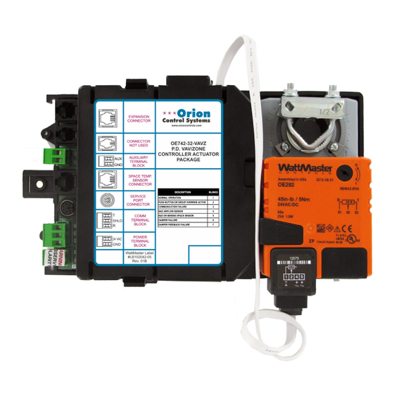
Page 6: Non-Modular Vav/Zone Controller Actuator Package Components
Overview Non-Modular VAV/Zone Controller Actuator Package Components Figure 3: OE742-32 Pressure Dependent Non-Modular VAV/Zone Controller Actuator Pkg. Components Figure 4: OE744-32 Pressure Independent Non-Modular VAV/Zone Controller Actuator Pkg. Components Non-Modular ZCAP Technical Guide... -
Page 7: Zone Controller Expansion Module Dimensions And Components
Overview Zone Controller Expansion Module Dimensions and Components Figure 5: OE325-01 Zone Controller Expansion Module Dimensions Figure 6: OE325-01 Zone Controller Expansion Module Components Non-Modular ZCAP Technical Guide... -
Page 8: Inputs And Outputs
Overview Inputs and Outputs The following inputs and outputs are available on the VAV/Zone Modular Service Tool DIN Connector Controller and the OE325-01 Zone Controller Expansion Module. For This connector is used to connect a cable between the Modular Service component locations of the inputs on the VAV/Zone Controller and VAV Tool or the USB-Link and the Non-Modular VAV/Zone Controller Zone Controller Expansion Module see Figures 3, 4, and 6. -
Page 9: Controller Installation & Wiring
Installation & Wiring Controller Installation & Wiring unit mounting surface or enclosure side walls. Use the included General self-tapping mounting screw to secure the enclosure base to the Correct wiring of the VAV/Zone Controller is the most important factor terminal unit sheet metal or terminal unit control enclosure sur- in the overall success of the controller installation process. -
Page 10: Zone Controller Actuator Package Wiring
Installation & Wiring Zone Controller Actuator Package Wiring snap track to it using sheet metal screws. Do not allow metal shavings to Wiring Considerations fall onto the circuit board. Re-attach the controller to the snap track. Be The OE325-01 Zone Controller Expansion Module connects to the sure the mounting location is close enough to the Non-Modular VAV/ Non-Modular VAV/Zone Controller Actuator Package by means of a Zone Controller Actuator Package so that the supplied modular cable... -
Page 11: Zone Controller Expansion Module Wiring
Installation & Wiring Zone Controller Expansion Module Wiring Figure 8: Zone Controller Expansion Module Wiring - Fan Terminals And/Or Staged Electric Heat Non-Modular ZCAP Technical Guide... - Page 12 Installation & Wiring Zone Controller Expansion Module Wiring Figure 9: Zone Controller Expansion Module Wiring - Fan Terminals And/Or Modulating Hot Water Heat Figure 10: Zone Controller Expansion Module Wiring - Fan Terminals And/Or 2 Position HW Heat Non-Modular ZCAP Technical Guide...
- Page 13 Installation & Wiring Zone Controller Expansion Module Wiring Figure 11: Zone Controller Expansion Module Wiring - Fan Terminals And/Or SCR Electric Heat Figure 12: Zone Controller Expansion Module Wiring - Fan Terminals And/Or Auxiliary Electric Heat Non-Modular ZCAP Technical Guide...
-
Page 14: Expansion Board & Communications Wiring
Installation & Wiring Expansion Board & Communications Wiring Figure 13: Zone Controller Expansion Module Wiring - Fan Terminals And/Or Auxiliary 2 Position HW Heat Figure 14: Communication & Power Wiring Diagram Non-Modular ZCAP Technical Guide... -
Page 15: Non-Modular Devices Transformer Sizing
Installation & Wiring Non-Modular Devices Transformer Sizing Figure 15: Non-Modular VAV/Zone Controller Actuator Package Transformer Sizing Non-Modular ZCAP Technical Guide... -
Page 16: Slaved Zone Damper Wiring
Installation & Wiring Slaved Zone Damper Wiring Two Slave Wiring Adapters (OE267) consisting of a slave wiring inter- Slaved Zone Damper Wiring face card and modular cable are supplied with the OE523 Round Slaved For large zones, it may be necessary to have more than one air damper Zone Damper, OE738 Slaved VAV/Zone Rectangular Damper Kit, and controlled by a Non-Modular VAV/Zone Controller Actuator Package the OE282-03 Slaved VAV/Zone Damper Kit. -
Page 17: Addressing & Powering Up
Start-Up & Commissioning Addressing & Powering Up For detailed information regarding communication wiring and connec- General tion for Interconnected and Networked systems, please see the Orion In order to have a trouble free start-up, it is important to follow a few System Installation &... -
Page 18: Initialization And Programming
Start-Up & Commissioning Initialization and Programming of the VAV/Zone Controller. You may use the Modular Service Tool, Initialization Modular System Manager, Tactio SI Touch Screen, System Manager On system power-up, the “STAT” LED is extinguished for a few seconds TS, or a personal computer with Prism software installed to access the and then the controller “flashes”... -
Page 19: Vav/Zone Configuration
Sequence of Operations VAV/Zone Configuration VAV/Zone Configuration & Setup Proportional Heating Signal If the box has hot water reheat using a proportional hot water valve, set There are a few configuration selections available which can be used this option to match the voltage signal required by the hot water valve to tailor the software operation to match the mechanical equipment the you are using. -
Page 20: Scheduling And Operation Modes
Sequence of Operations Scheduling and Operation Modes Scheduling Modes of Operation There are 7 possible modes of operation for the HVAC Unit and the Occupied/Unoccupied Mode VAV/Zone Controller. These modes are determined by the supply air The VAV/Zone Controller monitors the communications loop for its Oc- and/or space demand conditions. -
Page 21: Damper Positions
Sequence of Operations Damper Positions and Occupied Mode Sequences If the VAV/Zone Controller detects that the HVAC unit is in Supply Off Mode During unoccupied mode, the mode is considered ‘OFF’ if the space Air Heating mode, indicating that the air handler has activated its heat, temperature does not generate a heating mode or cooling mode based the heating airflow minimum will be substituted for the vent minimum on the unoccupied heating &... - Page 22 Sequence of Operations Occupied Mode Sequences Space Heating Mode Auxiliary Heat The Auxiliary Heat option allows for a separate setpoint that is different Occupied Space Heating mode is initiated by the temperature in the space from the other heating setpoints. The Auxiliary Heat Relay energizes at falling to within 0.5 ºF of the Occupied Heating Setpoint.
-
Page 23: Unoccupied Mode Sequences
Sequence of Operations Unoccupied Mode Sequences The damper/airflow is never allowed to modulate outside the user- Series Flow Fan Terminals adjusted minimum and the maximum setpoints. The maximum damper/ If the VAV/Zone Controller has been configured as a Series Fan Powered airflow setpoint applies to heating and cooling modes of operation only. - Page 24 Sequence of Operations Unoccupied Mode Sequences As with the Occupied Mode of operation, two different configurations Series Flow Fan Terminals are available for the Unoccupied Space Heating mode. If the box is If the VAV/Zone Controller has been configured as a Series Fan Powered configured to allow reheat during Supply Air Heating mode, the reheat terminal unit, the series fan will run continuously when the VAV/Zone relays can be activated even when the HVAC unit is in the Supply Air...
-
Page 25: Damper Control
Sequence of Operations Damper Control and Tenant Override Logs This sliding window allows the control to be much tighter on the smaller Damper Control terminal units than can be achieved on the larger terminal units as far as The damper position is calculated by the mode and demand from the CFM readings. -
Page 26: Zone Polling & Voting And Alarm Detection & Reporting
Sequence of Operations Zone Polling & Voting and Alarm Detection & Reporting Testing for Maverick Zones Zoning During the HVAC Mode decision process, a zone cannot be included in the Voting if it has been declared as Maverick. A zone is determined Description to be a Maverick if it stays 4 ºF below the Space Heating setpoint for 1 The Orion system can be configured to operate as a true zoning system... -
Page 27: Internal Trend Logging
Sequence of Operations Internal Trend Logging & Force Modes Note: For proper time and date stamping of the tenant log, you Internal Trend Logging must configure the VCM-X Controller to broadcast the time so that the VAV/Zone Controllers can read it and The VAV/Zone Controller continuously maintains an Internal Trend use it in their tenant and trend logs. -
Page 28: Led Troubleshooting
Troubleshooting LED Troubleshooting Using LEDs To Verify Operation “STAT” LED Operations As previously described, when the board is first powered up, the LED The VAV/Zone Controller is equipped with LEDs that can be used as will do the following: very powerful troubleshooting tools. The VAV/Zone Controller board •... -
Page 29: Other Checks
Troubleshooting Diagnostics Other Checks Actuator Check the Modular cable between the controller and the actuator. Be sure Space Temperature Sensor both ends of the cable are firmly connected to the mating connectors on the actuator and the VAV/Zone Controller board. Be sure the damper If the Space Temperature Sensor is not reading a valid temperature, moves freely and is not bound. -
Page 30: Temperature Sensor Testing
Troubleshooting Temperature Sensor Testing Temperature Sensor Testing Temperature – Resistance – Voltage for Type III 10 K Ohm Thermistor Sensors The following sensor voltage and resistance table is provided to aid in checking sensors that appear to be operating incorrectly. Many system Temp Resistance Voltage @ Input... -
Page 31: Modular And Digital Room Sensor Testing
Troubleshooting Modular and Digital Room Sensor Testing Figure 20: Testing Resistance & Voltage On Modular & Digital Room Sensors Non-Modular ZCAP Technical Guide... - Page 32 Zone Index Zone 0-10 VDC Voltage Signal....19 2-10 VDC Voltage Signal....19 C1....8 2 Position HW Heat C2....8 Wiring....12 C3....8 3 Relay Outputs....10 CFM Factor....19 3 Stage Heating Applications....8 Clockwise-to-Open Damper....19 Components Pressure Dependent VAV/Zone Controller Actuator Package....6 Actuator Pressure Independent VAV/Zone Diagnostics....29 Controller Actuator Package....6 Actuator Modular Connector....8...
- Page 33 Index Factory Mounted....9 Main Fan Status....19 Fan Enable....8 Maverick Zones....26 Fan Relay Staging....22 MiniLink PD Fan Terminals Addressing....17 Wiring....11 MiniLink Polling Device....25 Field Mounted Connecting to Power Comm Board....15 Directions....9 Modes of Operation....20 Force Modes....27 Modular Connectors Actuator....8 Power/Comm....8 Modular Devices Transformer Sizing....15 Heating Applications....8 Modular Room Sensor...
- Page 34 Zone Index Zone Relay Sequencing....8 Relay Staging....22 P1....8 Resistance Testing P2....8 Digital Room Sensor....31 Parallel Fan Powered Box With Reheat....19 Modular Room Sensor....31 Parallel Flow Fan Terminals....21, 23, 24 Reverse Acting....19 Polling....26 Round Zone Damper Kit Power/Comm Board Mounting....9 Connection Diagram....14 Sizing....9 Wiring....9, 14 Power/Comm Modular Connectors....8...
- Page 35 Index Tactio SI Touch Screen....18 Wiring Temperature/Resistance 2 Position HW Heat....12 Chart....30 Auxiliary 2 Position HW Heat....14 Temperature Sensor Auxiliary Electric Heat....13 Testing....30 Fan Terminals....11 Tenant Override Logs....25 Modulating Hot Water Heat....12 Thermistor Sensors Power/Comm Board....14 Resistance....30 SCR Electric Heat....13 Temperature....30 Slaved Zone....16 Testing....30...
- Page 36 Form: OR-NMZCAP-TGD-01D Printed in the USA November 2015 All rights reserved Copyright 2014 • • • WattMaster Controls Inc. 8500 NW River Park Drive Parkville, MO 64152 Phone (816) 505-1100 www.orioncontrols.com Fax (816) 505-1101...
Need help?
Do you have a question about the OE742-32-VAVZ and is the answer not in the manual?
Questions and answers