Table of Contents
Advertisement
Quick Links
Advertisement
Table of Contents

Related Manuals for Orion Control Systems OE326-23I-OR


Summary of Contents for Orion Control Systems OE326-23I-OR
- Page 1 www.orioncontrols.com VAV/Zone Controller Package Technical Guide...
- Page 2 www.orioncontrols.com AAON Controls Form: OR-VAVZP-TGD-01C 8500 NW River Park Drive · Parkville, MO 64152 All rights reserved. Toll Free Phone: 866-918-1100 © August 2018 WattMaster Controls, Inc. PH: (816) 505-1100 · FAX: (816) 505-1101 · AAON, Inc. assumes no responsibility for errors or E-mail: mail@wattmaster.com omissions in this document.
-
Page 3: Table Of Contents
TABLE OF CONTENTS OVERVIEW ............................4 Features and Applications ............................4 Parts and Descriptions ............................. 6 VAV/Zone Controller, Actuator, and Expansion Module Dimensions ..............10 Slaved Zone Damper Kit Dimensions ........................11 Rectangular Damper Kit Dimensions ........................11 Round Damper Kit Dimensions ..........................12 INSTALLATION AND WIRING ...................... -
Page 4: Overview
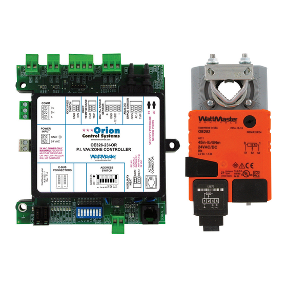
VAV/Zone Controller Packages VAV/Zone Controller Overview The OE744-03-OR Pressure Independent VAV/Zone Controller The OE326-23I-OR VAV/Zone Controller is designed for pres- Package includes the OE326-23I-OR VAV/Zone Controller, the sure independent VAV Box and Zone Damper applications. It OE282-01 Zone Damper Actuator with cable, and an Airfl ow is supplied with an integral Airfl... - Page 5 1 stage of electric heat, SCR electric heat, or modulating HW heat. OE744-03-OR Pressure Independent VAV/Zone Controller Package with Terminal Blocks Includes: OE326-23I-OR Pressure Independent. VAV/Zone COMM Controller with terminal blocks and airfl ow sensor and OE282-01 POWER INPUT Zone Damper Actuator with 3 foot phone jack cable.
-
Page 6: Parts And Descriptions
VAV/Zone Controller Expansion Module Includes: Expansion Module and 3 foot E-BUS modular cable. The Expansion Module is used in conjunction with the OE326-23I-OR and OE326-23D-OR VAV/Zone Controller and the OE742-03-OR and OE744-03-OR VAV/Zone Controller Packages and allows Fan & Heat... - Page 7 OVERVIEW Parts and Descriptions PART NO. PART DESCRIPTION ILLUSTRATION PAGE NO. OE520-06-PT Pressure Dependent Round Damper with Terminal OE520-08-PT Blocks OE520-10-PT OE520-12-PT The OE520-XX-PT Round Pressure Dependent Zone Damper Assembly with terminal block connectors consists of a round air OE520-14-PT Page 12 damper and the OE742-03-OR VAV/Zone Controller Package with OE520-16-PT...
- Page 8 Includes: Modular Adapter. The PCC modular cabling is not included. The PL102681 VAV/Zone Controller Modular Adapter is used to provide two Modular PCC connections to the OE326-23I-OR and OE326-23D-OR VAV/Zone Controllers and the OE742-03-OR and OE744-03-OR VAV/Zone Controller Packages so that these controllers can be used with PCC cables.
- Page 9 OVERVIEW Parts and Descriptions PART NO. PART DESCRIPTION ILLUSTRATION PAGE NO. OE361-13 CommLink 5 Communications Interface The CommLink 5 connects to your control system using a USB computer connection to provide direct on-site communications with the control system from a computer with the Prism 2 software installed. For remote communications, see the OE415-02 IP Module Kit.
-
Page 10: Vav/Zone Controller, Actuator, And Expansion Module Dimensions
WILL BE DAMAGED www.wattmaster.com E-BUS ADDRESS CONNECTORS SWITCH 2.05 2.62 BAUD LOOP BAUD 5.05 Figure 1: VAV/Zone Controller Dimensions - OE326-23I-OR Shown OE282 Damper Actuator 3.10" 1.35" 0.38” 2015 4.34" YS102532 REV R1 WATTMASTER CONTROLS, INC MADE IN USA 4.18"... -
Page 11: Slaved Zone Damper Kit Dimensions
OVERVIEW Slaved Zone Damper Kit & Rectangular Damper Kit Dimensions 4.15” OE282 Damper Actuator 0.38” 3.00” PL101824 Slave Wiring Interface Board 5.70” 0.75” PL101824 Slave Wiring Interface Board (2) Modular Cables 18.0 Figure 4: OE282-03 Slaved Zone Damper Kit Enclosure Base P.D. -
Page 12: Round Damper Kit Dimensions
OVERVIEW Round Damper Kit Dimensions Damper Housing Damper Housing ” ” 1/2” Foil Face 1/2” Foil Face Damper Blade Damper Blade Insulation Insulation And Shaft And Shaft P.I. Zone P.D. Zone Damper Actuato Damper Actua Controller Controller ” ” Air Flow Pickup Cross Control Base Cover Control Base Cover... -
Page 13: Installation And Wiring
INSTALLATION & WIRING Mounting and Installation Mounting & Installation 3. After positioning the damper actuator over the damper shaft, secure the damper actuator to the controller enclosure base using If you purchased the Round Zone Damper or Rectangular Zone the supplied L-bracket and 2 screws. Damper Kits from WattMaster, the controller and actuator are factory mounted and wired in the damper control enclosure. -
Page 14: Important Wiring Considerations
INSTALLATION & WIRING Important Wiring Considerations General Important Wiring Considerations Correct wiring of the VAV/Zone Controller is the most important Please carefully read and apply the following information when factor in the overall success of the controller installation process. wiring the VAV/Zone Controller Package. See Figure 10, page The VAV/Zone Controller wiring has been simplifi... - Page 15 INSTALLATION & WIRING Important Wiring Considerations Power Wiring Wiring Checks One of the most important checks to make before powering up One of the most important checks to make before powering up the system for the fi rst time is to confi rm proper voltage and the system for the fi...
-
Page 16: Device Transformer Sizing
INSTALLATION & WIRING Device Transformer Sizing 24 VAC Power - Transformer & Wire Sizing Considerations for Devices Without Modular Connectors Some installers like to use one large 24 VAC transformer to power several devices. This is allowable as long as polarity is maintained to each device Warning: on the transformer circuit. -
Page 17: Vav/Zone Communications Wiring
COMM Actuator Package As Required By Your POWER POWER INPUT INPUT www.orioncontrols.com www.orioncontrols.com 24 VAC 24 VAC Application. OE326-23I-OR OE326-23I-OR 24 VAC POWER ONLY P.I. VAV /ZONE CONTROLLER 24 VAC POWER ONLY P.I. VAV /ZONE CONTROLLER WARNING! POLARITY WARNING! POLARITY... -
Page 18: Vav/Zone Controller Inputs And Outputs
This sensor can be used for monitoring the discharge air tempera- ture of the terminal unit, round damper or rectangular damper If the OE326-23I-OR Pressure Independent VAV/Zone Control- used with the VAV/Zone Controller. The sensor is typically used ler is being used, the terminal unit’s pressure pick-up tube must when the terminal unit has reheat installed so the true temperature be connected with FRP tubing to the barb fi... -
Page 19: Expansion Module Outputs
INSTALLATION & WIRING VAV/Zone Controller Expansion Module Inputs and Outputs Other Connections VAV/Zone Controller Expansion Module Outputs E-BUS Connectors As previously stated, when you are using a fan terminal unit or The EBC E-BUS modular connectors are used to connect the have more than 1 stage of electric heat, have SCR electric heat, or optional OE325-03 VAV/Zone Controller Expansion Module to have modulating HW heat, the OE325-03 VAV/Zone Controller... -
Page 20: Vav/Zone Controller Package Wiring
INSTALLATION & WIRING VAV/Zone Controller Package Wiring Figure 10: VAV/Zone Controller Package with Terminal Blocks Wiring VAV/Zone Controller Package... -
Page 21: Expansion Module Wiring
INSTALLATION & WIRING VAV/Zone Controller Expansion Module Wiring Figure 11: VAV/Zone Controller Expansion Module Wiring - Fan Terminals And/Or Electric Staged Heat VAV/Zone Controller Package... - Page 22 INSTALLATION & WIRING VAV/Zone Controller Expansion Module Wiring 24 VAC Transformer Supplied & Wired by Others. Size For Remove Control Board Required HW Valve Load. from Snaptrack & Mount .1uF .1uF Snaptrack on Box 24VAC 1002 ALRM 1002 STAT 1002 COMM 1002 1002...
- Page 23 INSTALLATION & WIRING VAV/Zone Controller Expansion Module Wiring Figure 14: VAV/Zone Controller Expansion Module Wiring - Fan Terminals And/Or SCR Electric Heat VAV/Zone Controller Package...
-
Page 24: Slaved Zone Wiring
INTERFACE CARD WITH 24 GAUGE MINIMUM WIRE. SLAVED ZONE DAMPER ASSEMBLY #1 101824) BYPASS AND COMM SLAVE INTERFACE CARD POWER INPUT www.orioncontrols.com 24 VAC OE326-23I-OR P.I. VAV /ZONE CONTROLLER 24 VAC POWER ONLY WARNING! POLARITY MUST BE OBSERVED OR THE CONTROLLER WILL BE DAMAGED www.wattmaster.com... -
Page 25: Start-Up And Commissioning
START-UP & COMMISSIONING Addressing & Baud Rate Controller Addressing & Baud Rate When programming the VAV/Zone Controller on a Stand Alone or Interconnected System and you are asked to enter the Unit Setting ID, you would enter the address for the controller you wish to Before applying power for the fi... -
Page 26: Initialization And Operator Interfaces
START-UP & COMMISSIONING Initialization and Operator Interfaces Initialization If using the Modular Service Tool SD or the Modular System Manager SD for programming, refer to your HVAC Unit Control- On system power-up, the “STAT 1” & “STAT 2” LEDs are ex- ler’s Operator Interface SD Technical Guide. -
Page 27: Confi Guring The Vav/Zone Controller
START-UP & COMMISSIONING Configuration & Setup VAV/Zone Controller Confi guration Airfl ow @ 1” W.C. Across Airfl ow Pickup & Setup On Round Damper Damper Size K-Factor (CFM) Velocity (FPM) Confi guration can be accomplished by using either the Modular 6”... - Page 28 START-UP & COMMISSIONING VAV/Zone Controller Configuration & Setup Main Fan Status Auxiliary Heat The Auxiliary Heat option allows for a separate setpoint that is If the VAV/Zone Controller is installed on a non-fan powered diff erent from the other heating setpoints. The Auxiliary Heat box that has Reheat, set this option to Yes in order to enable box Reheat only when the HVAC unit fan is running.
-
Page 29: Sequence Of Operation
SEQUENCE OF OPERATIONS Scheduling & Operation Modes Scheduling Supply Air Cooling Mode (Based on HVAC Unit SAT) Occupied/ Unoccupied Mode This mode occurs when the Supply Air Temperature The VAV/Zone Controller monitors the communications loop for falls to less than the Space Temperature minus the its Occupied and Unoccupied mode of operation command. -
Page 30: Occupied Mode
SEQUENCE OF OPERATIONS VAV/Zone Occupied Mode Sequences Night Minimum When the HVAC unit is in the Supply Air Cooling Mode, the damper is normally held at the Minimum Cooling Position until This is the position that the damper moves to during the Unoc- the Space Temperature begins to rise above the Occupied Cool- cupied mode. - Page 31 SEQUENCE OF OPERATIONS VAV/Zone Occupied Mode Sequences Space Heating Mode Modulating ( Proportional) Heat Occupied Space Heating mode is initiated by the temperature in The VAV/Zone Controller Package with the Zone Controller the space falling to within 0.5ºF of the Occupied Heating Setpoint. Expansion Module provides an analog output for control of a Modulating Hot Water Valve or SCR Electric Heater.
-
Page 32: Unoccupied Mode
SEQUENCE OF OPERATIONS VAV/Zone Unoccupied Mode Sequences Series Flow Fan Terminals When the HVAC unit is in the Unoccupied Supply Air Cooling Mode, the damper will be held at the Night Minimum Position If the VAV/Zone Controller has been confi gured as a Series Fan until the Space Temperature begins to rise above the Cooling Powered terminal unit, the series fan relay will activate and run Setpoint. - Page 33 SEQUENCE OF OPERATIONS VAV/Zone Unoccupied Mode Sequences Space Heating Mode delay between staging. This prevents stages from activating at the same time. Once a heating stage has been activated, it must During Unoccupied Mode, the HVAC unit is normally off . Un- remain on for at least one minute.
-
Page 34: Damper Control
SEQUENCE OF OPERATIONS VAV/Zone Damper Control Parallel Flow Fan Terminals Example: If the VAV/Zone Controller has been confi gured as a Parallel 50% Remaining / 2% Integral = 25 moves to get to a Fan Powered terminal unit, the Parallel fan will run continuously 100% Maximum when the VAV/Zone Controller is in the Space Heating Mode no 25 Moves times 10 seconds = 250 seconds or a little... -
Page 35: Zoning
SEQUENCE OF OPERATIONS Zoning Zoning Zone Voting If a zone has been confi gured for the Voting mode, the Mini- The Orion Control System can be confi gured to operate as a true Link will perform the following tests based on the data received zoning system with the addition of a MiniLink PD 5. -
Page 36: Alarms
SEQUENCE OF OPERATIONS Alarms & Tenant Override Logs Alarm Detection and Reporting Tenant Override Logs The VAV/Zone Controller continuously performs self diagnostics If you require tenant billing for push-button override usage, a during normal operations to determine if any operating failures MiniLink PD 5 must be installed on each local loop. -
Page 37: Trend Logs
SEQUENCE OF OPERATIONS Internal Trend Logs & Force Modes or Overrides Internal Trend Logging Force Modes or Overrides In order to retrieve and utilize these logs, a computer with Prism The VAV/Zone Controller damper can be forced to one of several 2 computer software installed must be connected to the Orion positions. -
Page 38: Troubleshooting
TROUBLESHOOTING LED Troubleshooting Using LEDs To Verify Operation AUX HEAT RELAY LED - This yellow LED will blink to signal the Aux Heat Relay is enabled. The VAV/Zone Controller is equipped with LEDs that can be used to verify operation and perform troubleshooting. See Figure 18. CCW LED &... -
Page 39: Other Checks
TROUBLESHOOTING Diagnostics Other Checks Supply Air Temperature Sensor If you suspect the Supply Air Temperature Sensor is not reading Analog Space Temperature Sensor correctly, make sure the wiring terminal connections are tight and that any wiring splices are properly connected. You can If the Space Temperature Sensor is not reading a valid tempera- check the operation of the Supply Air Temperature Sensor by ture, make sure the wiring terminal connections are tight and... - Page 40 TROUBLESHOOTING Diagnostics Zone Damper Actuator VAV/Zone Controller Expansion Module Check the Modular cable between the controller and the actuator. If the VAV/Zone Controller Expansion Module does not seem to Be sure both ends of the cable are fi rmly connected to the mating operate correctly, fi...
-
Page 41: Temperature Sensor Testing
TROUBLESHOOTING Temperature Sensor Testing Temperature Sensor Testing The following sensor voltage and resistance table is provided to aid in checking sensors that appear to be operating incorrectly. Many system operating problems can be traced to incorrect sen- sor wiring. Be sure all sensors are wired per the wiring diagrams in this manual. - Page 42 TROUBLESHOOTING Temperature/Resistance/Voltage Table Temperature – Resistance – Voltage for Temperature – Resistance – Voltage for Type III 10 K Ohm Thermistor Sensors Type III 10 K Ohm Thermistor Sensors Temp Resistance Temp Resistance Voltage @ Input Voltage @ Input (VDC) (VDC) (ºF) (Ohms)
-
Page 43: Appendix - Vav/Zone Controller System Architecture
APPENDIX VAV/Zone Controller System Architecture Single Loop VAV/Zoning Multiple Loop VAV/Zoning If you have a single HVAC unit that will be using VAV terminal If you have a multiple HVAC units that will be using VAV Ter- units or are using a zoning system and don’t have any CV units minal Units or will be using a Zoning System and don’t have any you should select the Single Loop Zoning System. -
Page 44: Networked Single Loop System With Mlpd5
APPENDIX VAV/Zone Controller System Architecture COMM POWER INPUT www.orioncontrols.com 24 VAC OE326-23I-OR 24 VAC POWER ONLY P.I. VAV /ZONE CONTROLLER WARNING! POLARITY MUST BE OBSERVED OR THE CONTROLLER WILL BE DAMAGED www.wattmaster.com E-BUS ADDRESS CONNECTORS SWITCH BAUD LOOP BAUD COMM... -
Page 45: Networked Single Loop System With Mlpd5 And Commlink 5
APPENDIX VAV/Zone Controller System Architecture COMM POWER INPUT www.orioncontrols.com 24 VAC OE326-23I-OR 24 VAC POWER ONLY P.I. VAV /ZONE CONTROLLER WARNING! POLARITY MUST BE OBSERVED OR THE CONTROLLER WILL BE DAMAGED www.wattmaster.com E-BUS ADDRESS CONNECTORS SWITCH BAUD LOOP BAUD COMM... -
Page 46: Networked Multiple Loop System
Zone APPENDIX Zone VAV/Zone Controller System Architecture COMM POWER INPUT www.orioncontrols.com 24 VAC OE326-23I-OR 24 VAC POWER ONLY P.I. VAV /ZONE CONTROLLER WARNING! POLARITY MUST BE OBSERVED OR THE CONTROLLER WILL BE DAMAGED www.wattmaster.com E-BUS ADDRESS CONNECTORS SWITCH BAUD LOOP... -
Page 47: Index
INDEX 1 Stage Electric or On/Off HW Heat....18 2-Conductor Wire....14 Damper 24-Gauge....14 Control....34 24 VAC Power Terminal Block....19 Operating Mode....27 24 VAC-to-24 VAC....15 Positions....29 Diagnostics....39, 40 Digital Room Sensor....29 Troubleshooting....39 Actuator Digital Space Sensor....18 Diagnostics....40 Dimensions....10, 11, 12 Actuator Modular Connector....19 Discharge Temperature Sensor....13, 18 Address Switch Setting....25 Duct Temperature Sensor....18... - Page 48 Occupied/Unoccupied Mode....29 Internet/LAN Connection....9 OE210 - OE213.....7 IP Module Kit....9 OE217-02....7 OE217-03....7 OE230....7 OE231....7 K-Factor....27 OE282-01....6 OE282-03....7, 24 OE325-03....4, 6 OE326-23D-OR....4, 6 OE326-23I-OR....4, 6 LED Blink Codes....38 OE336-23-EM1....6 LED Locations....38 OE361-13....8 LEDs OE364-22....9 APP HB....38 OE364-23....9 Operation....38 OE364-23-OR....9 OS HB....38 OE366....9 STATUS 1....38...
- Page 49 INDEX Parallel Flow Fan Terminals....30, 32, 34 Scheduling....29 Polarity....14, 15 SCR Electric Heat....23 Power/Comm Board Sensors Connection Diagram....17 Mounting....13 Sizing....14 Temperature Sensor Testing....41 Wiring....14, 17 Series Flow Fan Terminals....30, 32, 33 Powering Up....25 Service Tool....26 Power Wiring....15 Setup Power Wiring Diagram....17 Zone/VAV....27 Pressure Dependent Rectangular Damper Kit....5 Single Loop VAV/Zoning....43...
- Page 50 Zone INDEX Zone VAV/Zone Damper Control....34 VAV/Zone Force Modes....37 Temperature/Resistance/Voltage Table....42 Vent Minimum....29 Temperature Sensor Testing....41 Voltage Tenant Override Logs....34, 36 Proper....15 Terminal Block....19 Voltage and Environment Requirements....14, 27 Testing for Maverick Zones....35 Voting Zone....27 Thermistor Sensors Resistance....42 Temperature....42 Testing....42 WDOG LED....38 Touch Screen System Manager....26 Window Open Detection....28...
- Page 51 NOTES VAV/Zone Controller VAV/Zone Controller Package...
- Page 52 Form: OR-VAVZP-TGD-01C Printed in the USA August 2018 All rights reserved Copyright 2018 AAON Controls • 8500 NW River Park Drive • Parkville, MO 64152 Phone (816) 505-1100 www.orioncontrols.com Fax (816) 505-1101...
Need help?
Do you have a question about the OE326-23I-OR and is the answer not in the manual?
Questions and answers