
Related Manuals for Embedded Solutions ADLPS104-150

Summary of Contents for Embedded Solutions ADLPS104-150
- Page 1 ADLPS104-150 Manual rev. 1.0 ADL Embedded Solutions Inc. 4411 Morena Blvd., Suite 101 San Diego, CA 92117-4345 P. +1 858 490-0597 F. +1 858 490-0599 e-mail: sales@adl-usa.com; web: http://www.adl-usa.com...
-
Page 3: Table Of Contents
Electrical Characteristics ........................24 Temperature Derating - Overall ....................24 Temperature Derating for each Controller .................. 24 Efficiency............................. 25 Mechanical Drawings ......................... 26 PCB: Mounting Holes ......................... 26 PCB: Pin-1 Dimensions ......................27 PCB: Cooling ..........................28 ADL Embedded Solutions ADLPS104-150 page 3... - Page 4 Chapter: Document History Important Notes page 4 ADL Embedded Solutions ADLPS104-150...
-
Page 5: Document History
First released version All company names, brand names, and product names referred to in this manual are registered or unregistered trademarks of their respective holders and are, as such, protected by national and international law. ADL Embedded Solutions ADLPS104-150 page 5... -
Page 6: Introduction
Solutions will be covered, provided a written claim for service under warranty is received by ADL Embedded Solutions no less then 30 days prior to the end of the warranty period of within 30 days of discovery of the defect – whichever comes first. Warranty coverage is contingent upon proper handling and operation of the product. -
Page 7: Description Of Safety Symbols
Operation of this equipment in a residential area is likely to cause harmful interference in which case the user will be required to correct the interference at his own expense. ADL Embedded Solutions ADLPS104-150 page 7... -
Page 8: Overview
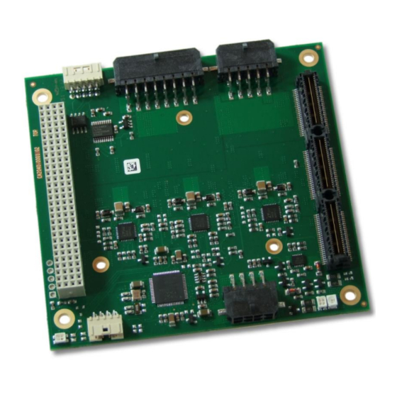
2 Overview 2.1 Features The ADLPS104-150 is a 150W PSU card, e.g. for use with industrial motherboards. Based on Linear Technology®'s LTC3858 2-Phase Synchronous Step-Down Controller, it is available in two product variants, V1 allowing an input voltage ranging from 7V to 36V, and V2 allowing 14V to 36V. Both variants offer S5V/2A, 5V/20A and 3.3V/5A outputs with V2 offering an additional 12V/10A output. -
Page 9: Featurelist
Except for 5V, all output voltages are switchable via PS-ON signal Monitoring Temperature monitoring Voltage monitoring Temperature Range 0-55°C (Extended temperature on request, please note the derating) Format 90.2mm x 95.5mm Standards DIN EN61000-6-2 DIN EN61000-6-4 ADL Embedded Solutions ADLPS104-150 page 9... -
Page 10: Connectors
"USB" p. 15 P401 "COM" p. 14 P500 "Power Input" p. 11 P501 "Power Output Peripherals" p. 12 P502 "Power Output CPU" p. 13 P600 "PC/104Plus Bus" p. 16 P601 "PC/104 PCIe" p. 18 page 10 ADL Embedded Solutions ADLPS104-150... -
Page 11: Power Input
Power Input Chapter: Connectors 3.2 Power Input The power supply of the ADLPS104-150 is realized via a 2x4-pin connector. Manufacturer Description Mating Connector Molex 43045-0809 WM1786-ND Since this is a 90 degree connector, the symbol in the drawing below OTICE represents the connector face as seen from the side (PCB on bottom) rather than from above. -
Page 12: Power Output Peripherals
12V / 10A ground ground 5V / 20A 5V / 20A ground ground 3.3V / 5A 3.3V 3.3V 3.3V / 5A ground ground S5V / 5A SVCC PWR_PWRGO powergood PS-ON# PWR_PSON# 8 PWRBTN# powerbutton page 12 ADL Embedded Solutions ADLPS104-150... -
Page 13: Power Output Cpu
5V / 20A 5V / 20A Product variants allowing an input voltage range from 7V to 36V will not OTICE have 12V output available. Pins 1 and 6 are "Reserved" on those variants. ADL Embedded Solutions ADLPS104-150 page 13... -
Page 14: Com
(PCB on bottom) rather than from above. Description Name Name Description termination resistor reserved receiver receiver transmitter transmitter termination resistor COMMODE Com mode ground SVCC standby supply page 14 ADL Embedded Solutions ADLPS104-150... -
Page 15: Usb
Chapter: Connectors 3.6 USB Via a 2x4-pin connector (FCI 98417-G61-08LF) the ADLPS104-150 is available as USB2.0 device. It is possible to read out technically relevant informations, such as temperature, voltage level etc. and to configure several settings. Please refer to your distributor for information on available software support. -
Page 16: Pc/104Plus Bus
PC/104Plus Bus 3.7 PC/104Plus Bus On the ADLPS104-150 installed PC/104Plus bus is by default no possibility to connect expansion cards. The connector block protects the board from mechanical damages. If the PSU gets connected to a CPU board via the PC/104Plus bus the bus provides power supply. - Page 17 5V power supply ground reserved PCI_RST# reset reserved reserved reserved ground There is a mounting option, which offers the by default not connected OTICE 3.3V lanes. ADL Embedded Solutions ADLPS104-150 page 17...
-
Page 18: Pc/104 Pcie
3.8 PC/104 PCIe The ADLPS104-150 offers a PCIe slot (type 1/type 2), on which by default pin 5 and 8 are not connected. As a mounting option those pins can be connected and the slot may be used to provide the PSU as USB device. - Page 19 ADL Embedded Solutions ADLPS104-150 page 19...
- Page 20 5V power supply 5V power supply 12V power supply Mounting options which provide a power input range from 7V to 36V do OTICE not offer a 12V output. On those boards pin C3 is "Reserved". page 20 ADL Embedded Solutions ADLPS104-150...
-
Page 21: State Leds
A reverse voltage on the input side is signalled by a dedicated LED (solid red). Status Codes LED: Color Interval Meaning None permanent Input voltage: polarity OK (or Power Off) permanent Input voltage: polarity inverted ADL Embedded Solutions ADLPS104-150 page 21... -
Page 22: Led: Input Voltage
A two-colored LED indicates the status of the input voltage. Status Codes LED: Color Interval Meaning none solid Power Off Green solid Input voltage OK solid Input voltage too low / too high / overcurrent page 22 ADL Embedded Solutions ADLPS104-150... -
Page 23: Led: Output Voltage
Status information regarding the output voltage is provided by a two-colored LED. Status Codes LED: Color Interval Meaning none Power Off or S5V OK while PWRGD de-asserted Green solid All Output voltages OK solid S5V is Off ADL Embedded Solutions ADLPS104-150 page 23... -
Page 24: Electrical Characteristics
The following picture shows the output power in relation to temperature: 5.2 Temperature Derating for each Controller The ADLPS104-150 can be ordered for operation in an extended ambient temperature range of -40° C to 85° C. In this case, derating applies for the temperatures above 70° C as follows:... -
Page 25: Efficiency
Efficiency Chapter: Electrical Characteristics 5.3 Efficiency The picture below shows the efficiency data for various output voltages. The data has been measured at room temperature with 24V input voltage. ADL Embedded Solutions ADLPS104-150 page 25... -
Page 26: Mechanical Drawings
PCB: Mounting Holes 6 Mechanical Drawings Use a sufficient thermal solution! OTICE In order to achieve an optimal efficiency, we advise against using the ADLPS104-150 without a sufficient thermal solution. 6.1 PCB: Mounting Holes page 26 ADL Embedded Solutions ADLPS104-150... -
Page 27: Pcb: Pin-1 Dimensions
PCB: Pin-1 Dimensions Chapter: Mechanical Drawings 6.2 PCB: Pin-1 Dimensions ADL Embedded Solutions ADLPS104-150 page 27... -
Page 28: Pcb: Cooling
Chapter: Mechanical Drawings PCB: Cooling 6.3 PCB: Cooling The ADLPS104-150 needs an appropriate cooling solution. The components which need attention are colored in the drawings below. Most of these components carry a current on the outside of their metal housing. Therefore, only isolating materials can be used for the direct OTICE contact between cooling solution and component.
Need help?
Do you have a question about the ADLPS104-150 and is the answer not in the manual?
Questions and answers