Table of Contents
Advertisement
Available languages
Available languages
Quick Links
The Ultimate in Fall Protection
FORM NO: 5903176
REV: B
EN795:1996
8
CE Type Test
CE Production Quality Control
No. 0086
BSI Product Services
P.O. Box 6221, Kitemark Court
P.O. Box 6221, Kitemark Court
Davy Avenue
Milton Keynes
MK1 9EP UK
Class B
9
48
No. 0086
BSI Product Services
Davy Avenue
Milton Keynes
MK1 9EP UK
8563159
ADVANCED SYSTEM
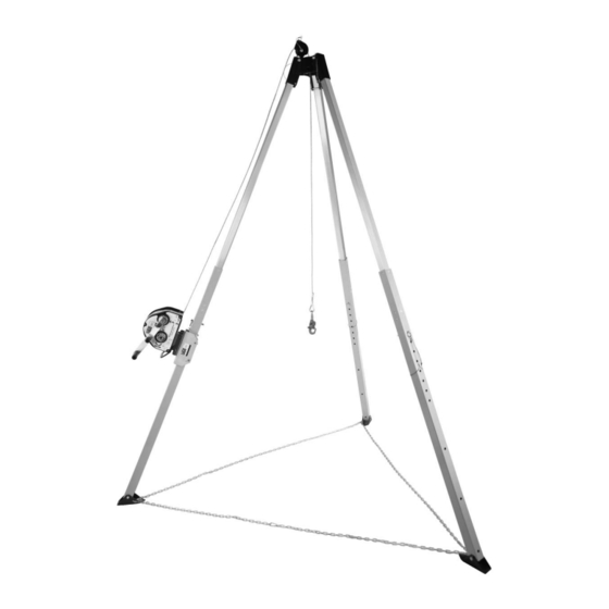
UCT-1000 Tripod
78
Model Number: 8563159
INSTRUCTION MANUAL
© Copyright 2013, Capital Safety
49
5902392
Advertisement
Table of Contents

Related Manuals for DBI SALA UCT-1000


Summary of Contents for DBI SALA UCT-1000
- Page 1 ADVANCED SYSTEM EN795:1996 Class B UCT-1000 Tripod Model Number: 8563159 CE Type Test CE Production Quality Control INSTRUCTION MANUAL The Ultimate in Fall Protection No. 0086 No. 0086 BSI Product Services BSI Product Services P.O. Box 6221, Kitemark Court P.O. Box 6221, Kitemark Court...
- Page 3 UCT-1000 TRIPOD SETUP AND WINCH INSTALLATION INSTRUCTIONS A) Setting up the UCT-1000 Tripod 1. Stand collapsed Tripod[1] on fl oor with feet down (See Fig. 1 ). 2. Remove leg retainer pins[2] from 3 places in tripod head ( See Fig. 1).
- Page 4 UCT-1000 TRIPOD SETUP & WINCH INSTALLATION INSTRUCTIONS B) Installing the Winch to UCT-1000 Tripod FIG. 4a FIG. 4b Once tripod has been set up & leveled(Fig. 4a) install the winch assembly as follows: 1. Lay the tri-pod on its side as shown in (Fig.
- Page 5 UCT-1000 TRIPOD SETUP & WINCH INSTALLATION INSTRUCTIONS FIG. 5a B) Installing the Winch to UCT-1000 Tripod c'ont from page 2 3. Install two winch bracket retainer pins[10] through winch bracket[9] behind tripod leg[7]. 4. Slide winch assembly[8] up / down tripod leg[7] to desired location, and install winch bracket retainer pin[11].
-
Page 6: General Specifications
Winch Mounting Bracket Top Pulley Ass'y DESCRIPTION The CSG UCT-1000 Tripod combines the quality and user friendly performance of all CSG Safety Systems Safety equipment with the economy of the basic tripod. Constructed of lightweight tubular aluminum with a rugged steel head assembly, the UCT-1000 tripod can be combined with a variety of pulleys, winches and fall-arrest devices to meet a wide range of confi... - Page 7 T-300/T-1000 TRIPOD SYSTEM SETUP AND WINCH INSTALLATION INSTRUCTIONS INSTALLATION OF WINCHES, SELF-RETRACTING LIFELINES ( SRL's), WORK POSITIONING AND FALL-ARREST DEVICES NOT MANUFACTURED BY CAPITAL SAFETY GROUP. Your T-1000 TRIPOD SYSTEM can be used as a support structure for various types of safety devices. Some of these can mount directly to the anchor point at the top of the tripod head, while others may require an adapter bracket available from your dealer.
- Page 8 T-300/T-1000 TRIPOD SYSTEM INSPECTION LOG BOOK MODEL # SERIAL # MFG. DATE HOIST INSPECTION LOG: (SAMPLE FORM - Copy to start inspection log book) TYPE OF INSPECTION: DAILY WEEKLY ANNUALLY Date of Inspection (d / m / y) Inspected By: LABELS DAMAGE...
- Page 9 TRÉPIED UCT-1000 INSTRUCTIONS DE MONTAGE ET D’INSTALLATION DU TREUIL A) Installation du trépied UCT-1000 1. Posez le trépied replié [1] sur le sol avec les pieds orientés vers le bas (voir Fig. 1). 2. Retirez les broches de retenue des pieds [2] des trois emplacements de la tête du trépied (voir Fig.
- Page 10 TRÉPIED UCT-1000 INSTRUCTIONS DE MONTAGE ET D’INSTALLATION DU TREUIL B) Installation du treuil avec le trépied UCT-1000 FIG. 4a Une fois l’installation et la mise à niveau du trépied Fig. 4b effectuées (Fig. 4a), installer l’assemblage de treuil en suivant les instructions ci-dessous : 1.
- Page 11 TRÉPIED UCT-1000 INSTRUCTIONS DE MONTAGE ET D’INSTALLATION DU TREUIL FIG. 5a B) Installation du treuil avec le trépied UCT-1000 suite à la page 2 3. Installer deux broches de retenue de support de treuil [10] sur le support de treuil [9] derrière le pied du trépied [7].
-
Page 12: Caractéristiques Générales
Support de montage du treuil Assemblage de la poulie supérieure DESCRIPTION Le trépied UCT-1000 des systèmes de sécurité CSG allie la performance de qualité et de facilité d’utilisation de tous les équipements des systèmes de sécurité CSG à l’économie du trépied de base. Constitué... - Page 13 SYSTÈME DE TRÉPIED T-300/T-1000 INSTRUCTIONS DE MONTAGE ET D’INSTALLATION DU TREUIL INSTALLATION DES TREUILS, LIGNES DE VIE AUTORÉTRACTABLES (SRL), DISPOSITIF DE POSITIONNEMENT ET DISPOSITIFS D’ARRÊT DE CHUTE NON FABRIQUÉS PAR CAPITAL SAFETY GROUP Le SYSTÈME DE TRÉPIED T-1000 peut être utilisé comme structure de support pour différents types de dispositifs de sécurité.
- Page 14 SYSTÈME DE TRÉPIED T-300/T-1000 LIVRE DE RELEVÉ D’INSPECTION MODÈLE N° Nº DE SÉRIE FAB. DATE RELEVÉ D’INSPECTION DE L’ÉLÉVATEUR : (EXEMPLE DE FORMULAIRE - Copier pour commencer le journal d’inspection) TYPE D’INSPECTION : TOUS LES JOURS TOUTES LES SEMAINES TOUS LES ANS Date d’inspection (j/m/a) Inspecté...
- Page 15 TREPPIEDE UCT-1000 ISTRUZIONI PER IL MONTAGGIO E L’INSTALLAZIONE DEL VERRICELLO A) Montaggio del treppiede UCT-1000 1. Posizionare il treppiede chiuso [1] verticalmente sul pavimento con i piedini appoggiati a terra (Fig. 1). 2. Rimuovere i perni delle gambe [2] da tre punti della testa del treppiede (Fig.
- Page 16 TREPPIEDE UCT-1000 ISTRUZIONI PER IL MONTAGGIO E L’INSTALLAZIONE DEL VERRICELLO B) Montaggio del verricello sul treppiede UCT-1000 FIG. 4a FIG. 4b Una volta montato e assestato il treppiede (Fig. 4), installare il gruppo del verricello come descritto. 1. Mettere il treppiede di lato come mostrato nella Fig. 4b, con la gamba con la puleggia [14] rivolta verso l’alto.
- Page 17 TREPPIEDE UCT-1000 ISTRUZIONI PER IL MONTAGGIO E L’INSTALLAZIONE DEL VERRICELLO FIG. 5a B) Montaggio del verricello sul treppiede UCT-1000 segue da pagina 2 3. Installare due fermi della staffa del verricello [10] attraverso la staffa del verricello [9] dietro la gamba del treppiede [7].
-
Page 18: Specifi Che Generali
CSG Safety Systems alla convenienza di un modello base di treppiede. Realizzato in alluminio tubolare leggero, con gruppo di testa in acciaio ruvido, il treppiede UCT-1000 può combinarsi con tutta una serie di pulegge, verricelli e dispositivi anticaduta per soddisfare un’ampia gamma di requisiti di accesso/... - Page 19 TREPPIEDE T-300/T-1000 ISTRUZIONI PER IL MONTAGGIO E L’INSTALLAZIONE DEL VERRICELLO MONTAGGIO DI VERRICELLI, CAVI DI SICUREZZA AUTORETRATTILI ( SRL), DISPOSITIVI DI POSIZIONAMENTO OPERATIVO E ANTICADUTA NON FABBRICATI DA CAPITAL SAFETY GROUP Il treppiede T-1000 può essere utilizzato come struttura di sostegno per vari tipi di dispositivi di sicurezza. Alcuni dispositivi possono essere montati direttamente sul punto di ancoraggio sopra la testa del treppiede, mentre altri richiedono una staffa di adattamento, che può...
- Page 20 TREPPIEDE T-300/T-1000 REGISTRO DI ISPEZIONE MODELLO N. N. DI SERIE DATA DI PROD. REGISTRO DI ISPEZIONE DEL DISPOSITIVO DI SOLLEVAMENTO: (MODULO ESEMPLIFICATIVO - Copia per iniziare il registro di ispezione) TIPO DI ISPEZIONE: OGNI GIORNO OGNI SETTIMANA OGNI ANNO Data di ispezione (g/m/a) Controllato da:...
- Page 21 STATIV UCT-1000 AUFSTELLUNGS- UND MONTAGEANLEITUNG FÜR DIE WINDE A) Aufstellen des Stativs UCT-1000 1. Das zusammengelegte Stativ[1] mit den Füßen nach unten auf den Boden stellen (siehe Abb. 1 ). 2. Die Beinhaltestifte[2] an drei Stennen vom Stativkopf entfernen (siehe Abb. 1).
- Page 22 STATIV UCT-1000 AUFSTELLUNGS- UND MONTAGEANLEITUNG FÜR DIE WINDE B) Installieren der Winde am Stativ UCT-1000 ABB. 4a ABB. 4b Nach dem Aufstellen und Ausrichten des Stativs (Abb. 4a) die Windenbaugruppe wie folgt installieren: 1. Das Stativ entsprechend der Darstellung in Abb.
- Page 23 STATIV UCT-1000 AUFSTELLUNGS- UND MONTAGEANLEITUNG FÜR DIE WINDE ABB. 5a B) Installieren der Winde am Stativ UCT-1000 Forts. von Seite 2 3. Zwei Haltestifte für die Windenhalterung[10] durch die Windenhalterung[9] hinter dem Stativbein[7] führen. 4. Die Windenbaugruppe[8] entlang dem Stativbein[7] nach oben/unten an die gewünschte Stelle schieben und den Haltestift...
-
Page 24: Allgemeine Technische Daten
Windenhalterung Baugruppe der oberen Umlenkrolle BESCHREIBUNG Das Stativ CSG UCT-1000 vereint in sich die Qualität und benutzerfreundliche Leistung aller Sicherheitsausrüstungen von CSG Safety Systems mit der Wirtschaftlichkeit eines Stativ-Grundgeräts. Das Stativ UCT-1000 wird in Leichtbauweise aus Aluminiumrohr mit einer robusten Kopfbaugruppe aus Stahl hergestellt und lässt sich mit einer Vielfalt von Umlenkrollen, Winden und... - Page 25 STATIV UCT-1000 AUFSTELLUNGS- UND MONTAGEANLEITUNG FÜR DIE WINDE MONTAGE VON WINDEN, AUTOMATISCH EINZIEHENDEN SICHERUNGSSEILEN (SRLs), POSITIONIERUNGS- UND FALLSCHUTZVORRICHTUNGEN, DIE NICHT VON Capital Safety Group LTD. HERGESTELLT WURDEN Ihr STATIVSYSTEM T-1000 kann als Aufl ager für verschiedene Typen von Sicherheitsgeräten genutzt werden.
- Page 26 STATIVSYSTEM T-300/T-1000 KONTROLLPROTOKOLL MODELLNR. SERIENNR. HERST.- DATUM HEBEZEUG-KONTROLLPROTOKOLL: (MUSTERFORMULAR – Kopieren, um Kontrollprotokoll anzulegen) ART DER KONTROLLE: TÄGLICH WÖCHENTLICH JÄHRLICH Kontrolldatum (T / M / J) Kontrolliert von: ETIKETTEN BESCHÄDIGUNGEN KORROSION BEFESTIGUNGSMITTEL UMLENKROLLEN ROLLE ANKERSPITZEN WINDENHALTERUNG SRL-HALTERUNG SCHWEISSNÄHTE SONSTIGES BEMERKUNGEN:...
- Page 27 TRÍPODE UCT-1000 INSTRUCCIONES DE MONTAJE E INSTALACIÓN DEL CABRESTANTE A) Montaje del trípode UCT-1000 1. Coloque el trípode [1] en posición replegada en el suelo con las bases de las patas hacia abajo (vea la Fig. 1). 2. Retire los pasadores de retención de las patas [2] de los 3 lugares del cabezal del trípode (vea la Fig.
- Page 28 TRÍPODE UCT-1000 INSTRUCCIONES DE MONTAJE E INSTALACIÓN DEL CABRESTANTE B) Instalación del cabrestante en el trípode UCT-1000 FIG. 4a FIG. 4b Una vez que haya montado y nivelado el trípode (Fig. 4a), instale el conjunto del cabrestante de la siguiente manera: 1.
- Page 29 TRÍPODE UCT-1000 INSTRUCCIONES DE MONTAJE E INSTALACIÓN DEL CABRESTANTE FIG. 5a B) Instalación del cabrestante en el trípode UCT-1000 continuación de la página 2 3. Instale dos pasadores de retención [10] a través del soporte del cabrestante [9] que se encuentra detrás de la pata del trípode [7].
-
Page 30: Especificaciones Generales
Conjunto de la polea superior DESCRIPCIÓN El trípode UCT-1000 de CSG combina la calidad y el funcionamiento simple de todos los equipos de CSG Safety Systems con la economía de un trípode básico. El trípode UCT-1000, construido en aluminio tubular ligero con un conjunto de cabezal de acero resistente, se puede combinar con varias poleas, cabrestantes y dispositivos de protección contra caídas. - Page 31 SISTEMA DE TRÍPODE T-300/T-1000 INSTRUCCIONES DE MONTAJE E INSTALACIÓN DEL CABRESTANTE INSTALACIÓN DE CABRESTANTES, CABOS ANTICAÍDAS AUTORREPLEGABLES (DE SRL), DISPOSITIVOS DE POSICIONAMIENTO DE TRABAJO Y DE PROTECCIÓN CONTRA CAÍDAS NO FABRICADOS POR CAPITAL SAFETY GROUP LTD. El SISTEMA DE TRÍPODE T-1000 puede utilizarse como estructura de apoyo para varios tipos de dispositivos de seguridad.
-
Page 32: Fecha De Fabricación
SISTEMA DE TRÍPODE T-300/T-1000 LIBRO DE REGISTRO DE INSPECCIONES N.º DE MODELO N.º DE SERIE FECHA DE FABRICACIÓN REGISTRO DE INSPECCIONES DEL SISTEMA DE IZADO: (FORMULARIO DE MUESTRA: cópielo para comenzar con el libro de registros de inspección) ... - Page 33 TRIPÉ UCT-1000 INSTRUÇÕES DE INSTALAÇÃO DO GUINCHO E MONTAGEM A) Montar o tripé UCT-1000 1. Apoie os pés do tripé [1] fechado no chão (Consulte a Fig. 1 ). 2. Remova os pinos de bloqueio das pernas [2] de 3 locais na cabeça do tripé...
- Page 34 TRIPÉ UCT-1000 INSTRUÇÕES DE INSTALAÇÃO DO GUINCHO E MONTAGEM B) Instalar o guincho no tripé UCT-1000 FIG. 4a FIG. 4b Assim que o tripé estiver montado e nivelado (Fig. 4a), instale a estrutura do guincho da seguinte forma: 1. Apoie o tripé na sua parte lateral conforme apresentado na (Fig.
- Page 35 TRIPÉ UCT-1000 INSTRUÇÕES DE INSTALAÇÃO DO GUINCHO E MONTAGEM FIG. 5a B) Instalar o guincho no tripé UCT-1000 continuação da página 2 3. Instale dois pinos de bloqueio do guincho [10] através do suporte do guincho [9] por trás da perna do tripé [7].
-
Page 36: Especifi Cações Gerais
CSG com a economia do tripé básico. Construído em alumínio tubular leve com uma estrutura principal em aço reforçado, o tripé UCT-1000 pode ser combinado com uma grande variedade de roldanas, guinchos e dispositivos de paragem de queda de modo a ser compatível com um grande número de requisitos de entrada/... - Page 37 SISTEMA DE TRIPÉ T-300/T-1000 INSTRUÇÕES DE INSTALAÇÃO DO GUINCHO E MONTAGEM INSTALAÇÃO DE GUINCHOS, CORDAS DE SEGURANÇA AUTO-RETRÁCTEIS, DISPOSITIVOS DE POSICIONAMENTO NO TRABALHO E PARAGEM DE QUEDA NÃO FABRICADOS PELO CAPITAL SAFETY GROUP. O seu SISTEMA DE TRIPÉ T-1000 pode ser utilizado como uma estrutura de apoio para vários tipos de dispositivos de segurança. Alguns destes podem ser montados directamente no ponto de ancoragem na parte superior da estrutura principal do tripé, ao passo que outros podem necessitar de um suporte adaptador, disponível junto do seu revendedor.
-
Page 38: Data De Fabrico
SISTEMA DE TRIPÉ T-300/T-1000 LIVRO DE REGISTO DE INSPECÇÕES N.º DO MODELO N.º DE SÉRIE DATA DE FABRICO REGISTO DE INSPECÇÕES DO ELEMENTO ELEVATÓRIO: (FORMULÁRIO MODELO - Copiar para iniciar o livro de registo de inspecções) TIPO DE INSPECÇÃO: DIARIAMENTE SEMANALMENTE ANUALMENTE... - Page 39 DRIEPOOT UCT-1000 INSTRUCTIES VOOR OPSTELLEN EN INSTALLATIE VAN LIER A) De driepoot UCT-1000 opstellen 1. Plaats de ingeklapte driepoot [1] op de vloer met de pootjes naar beneden (Zie afb. 1 ). 2. Verwijder de pootvergrendelingspinnen [2] uit de kop van de driepoot (Zie afb. 1).
- Page 40 DRIEPOOT UCT-1000 INSTRUCTIES VOOR OPSTELLEN EN INSTALLATIE VAN LIER B) Installatie van de lier op driepoot UCT-1000 AFB. 4a AFB. 4b Zodra de driepoot is opgesteld en waterpas staat (afb. 4a) installeert u als volgt de lierconstructie: 1. Leg de driepoot op zijn kant zoals afgebeeld in (afb.
- Page 41 DRIEPOOT UCT-1000 INSTRUCTIES VOOR OPSTELLEN EN INSTALLATIE VAN LIER AFB. 5a B) Installatie van de lier op driepoot UCT-1000 vervolg van pag. 2 3. Plaats twee lierbeugel-vergrendelingspinnen [10] door de lierbeugel[9] achter de poot van de driepoot[7]. 4. Schuif de lierconstructie [8] langs de poot...
-
Page 42: Algemene Specifi Caties
Lier Digital 100 Lierbevestigingsbeugel Bovenkatrolconstructie BESCHRIJVING In de CSG UCT-1000 driepoot worden de kwaliteit en gebruiksvriendelijkheid van alle veiligheidsmiddelen van CSG Safety Systems gecombineerd met de gunstige prijs van een simpele driepoot. De driepoot UCT-1000 bestaat uit lichtgewicht aluminium buizen met... - Page 43 DRIEPOOTSYSTEEM T-300/T-1000 INSTRUCTIES VOOR OPSTELLEN EN INSTALLATIE VAN LIER INSTALLATIE VAN LIEREN, ZELFTERUGLOPENDE REDDINGSLIJNEN (SELF-RETRACTING LIFELINES, SRL's) EN WERKPOSITIONERINGS- EN VALSTOPAPPARATUUR DIE NIET GEPRODUCEERD ZIJN DOOR CAPITAL SAFETY GROUP. Het DRIEPOOTSYSTEEM T-1000 kan worden gebruikt als ondersteuningsstructuur voor verschillende soorten veiligheidsmiddelen.
- Page 44 DRIEPOOTSYSTEEM T-300/T-1000 INSPECTIELOGBOEK MODELNR. SERIENR. FABR. DATUM INSPECTIELOGBOEK HIJSSYSTEEM (VOORBEELDFORMULIER - kopieer dit om een inspectielogboek te maken) SOORT INSPECTIE: DAGELIJKS WEKELIJKS JAARLIJKS Inspectiedatum (d/m/j) Geïnspecteerd door: LABELS SCHADE CORROSIE BEVESTIGINGSMATERIALEN KATROLLEN ROLLER VERANKERINGSPUNTEN LIERBEUGEL BEUGEL SRL's LASSEN OVERIG OPMERKINGEN:...
- Page 46 WARNING: AVERTISSEMENT : Installers shall ensure the suitability of base materials into which Les installateurs s’assureront que les matériaux de base structural anchor devices are fi xed. dans lesquels les dispositifs d’ancrage structuraux sont fi xés sont adaptés. Where an anchor device is intended to be used exclusively for personal protective Dans le cas où...
-
Page 47: Limited Lifetime Warranty
LIMITED LIFETIME WARRANTY Garantie limitée à vie Warranty to End User: CAPITAL SAFETY warrants to the original end user (“End User”) that its Garantie de l’utilisateur fi nal : CAPITAL SAFETY garantit à l’utilisateur fi nal d’origine (« products are free from defects in materials and workmanship under normal use and service. This Utilisateur fi... - Page 48 The Ultimate in Fall Protection CSG USA & Latin America CSG Canada CSG Northern Europe 3833 SALA Way 260 Export Boulevard 5a Merse Road Red Wing, MN 55066-5005 Mississauga, ON L5S 1Y9 North Moons, Moat Toll Free: 800.328.6146 Phone: 905.795.9333 Reditch, Worcestershire, UK Phone: 651.388.8282 Toll-Free: 800.387.7484...
Need help?
Do you have a question about the UCT-1000 and is the answer not in the manual?
Questions and answers