Bunn FMD-2 Operating & Service Manual
Bunn fmd-2: user guide
Hide thumbs
Also See for FMD-2:
- Operating & service manual (40 pages) ,
- Illustrated parts catalog (24 pages) ,
- Service & repair manual (71 pages)
Table of Contents
Advertisement
Quick Links
BUNN
OPERATING & SERVICE MANUAL
28364.0000D 08/02 ©1998 Bunn-O-Matic Corporation
BUNN-O-MATIC CORPORATION
POST OFFICE BOX 3227
SPRINGFIELD, ILLINOIS 62708-3227
PHONE: (217) 529-6601 FAX: (217) 529-6644
®
(prior to S/N FMD0013000)
S E
E A
E L
N R
H E
, T
L L
F U
/ 3
S 2
P I
C U
I L
N T
N U
T O
U T
D B
O L
d H
a n
S H
L L
P U
F U
IN G
/ 3
R N
S 2
W A
T
P I
!
H O
I D
C U
U
E N
Q
L I
W H
E
A C
E
N
P L
E R
T O
P H
U T
C U
E B
A S
L E
R E
E
A C
E
P L
E R
P H
C U
E
A C
E
P L
E R
P H
C U
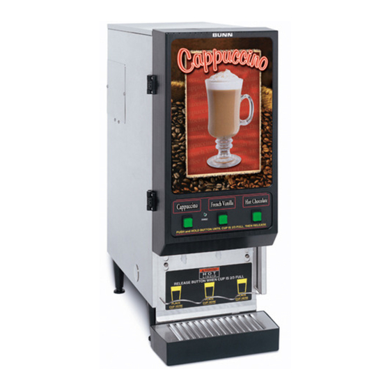
FMD-2
FMD-3
www.bunnomatic.com
Advertisement
Table of Contents

Related Manuals for Bunn FMD-2


Summary of Contents for Bunn FMD-2
- Page 1 BUNN OPERATING & SERVICE MANUAL BUNN-O-MATIC CORPORATION 28364.0000D 08/02 ©1998 Bunn-O-Matic Corporation ® IN G POST OFFICE BOX 3227 SPRINGFIELD, ILLINOIS 62708-3227 PHONE: (217) 529-6601 FAX: (217) 529-6644 FMD-2 FMD-3 (prior to S/N FMD0013000) www.bunnomatic.com...
-
Page 2: User Notices
REPAIR, REPLACEMENT OR REFUND. In no event shall BUNN be liable for any other damage or loss, including, but not limited to, lost profits, lost sales, loss of use of equipment, claims of Buyer’s customers, cost of capital, cost of down time, cost of substitute equipment, facilities or services, or any other special, incidental or consequential damages. - Page 3 USER NOTICES (cont.) 00656.0000 00831.0000 160° 190° HEATER TEMPERATURE ADJUSTMENT 26527.0002 THERMOSTAT ASSEMBLY BUNN-O-MATIC CORP 120VAC ® MECHANICAL THERMOSTAT ELECTRONIC THERMOSTAT 28368.0000 26536.0002 RELEASE BUTTON WHEN CUP IS 2/3 FULL PLACE PLACE CUP HERE CUP HERE FMD-2 FMD-3 28328.00003 28328.0000...
-
Page 4: Initial Setup
It can be purchased direct from Bunn-O-Matic (part number 00326-0000). Bunn-O-Matic does not recommend the use of a saddle valve to install the dispenser. The size and shape of the hole made in the supply line by this type of device may restrict water flow. -
Page 5: Initial Fill & Heat
NOTE - The mixing chamber must drain at the end of each dispense. COLD BEVERAGE SET-UP (OPTIONAL) Cold beverages may be dispensed from the left dispense position on the FMD-2 & FMD-3 models. Simply place the HOT/COLD switch near the left whipper chamber in the “COLD” (upper) position. -
Page 6: Troubleshooting
Hopper dispense rate with optional 32 tooth gear and auger wire is 6 to 9 grams per second. A troubleshooting guide is provided to suggest probable causes and remedies for the most likely problems encountered. If the problem remains after exhausting the troubleshooting steps, contact the Bunn-O-Matic Technical Service Department. - Page 7 TROUBLESHOOTING (cont.) PROBLEM Product will not dispense PROBABLE CAUSE 1. No water 2. No power or incorrect voltage to the dispenser 3. Dispense switch 4. Dispense solenoid valve (Hot or Cold) 5. Solenoid valve (Inlet) 6. Level control board and probe 7.
- Page 8 TROUBLESHOOTING (cont.) PROBLEM Product will not dispense (cont.) Water is not hot Spitting or excessive steaming PROBABLE CAUSE 9. Water strainer 10. Lime build-up CAUTION - Tank and tank compo- nents should be delimed regularly depending on local water conditions. Excessive mineral build-up on stain- less steel surfaces can initiate corro- sive reactions resulting in serious...
- Page 9 TROUBLESHOOTING (cont.) PROBLEM Dripping from dispense tip Water flows into tank continuously Product overflows container PROBABLE CAUSE 1. Lime build-up CAUTION - Tank and tank compo- nents should be delimed regularly depending on local water conditions. Excessive mineral build-up on stain- less steel surfaces can initiate corro- sive reactions resulting in serious leaks.
- Page 10 TROUBLESHOOTING (cont.) PROBLEM Weak product PROBABLE CAUSE 1. Water temperature 2. Whipper motor 3. Frother 4. Dispense solenoid valve (Hot or Cold) 5. Auger drive 6. Auger spring 7. Auger motor 8. Rinse/Run switch REMEDY Place an empty container beneath the dispense tip.
- Page 11 TROUBLESHOOTING (CONT.) PROBLEM Dispenser is making unusual noises Excess dust Display not lit PROBABLE CAUSE 1. Plumbing Lines 2. Water Supply 3. Tank Heater 1. Fan 2. Hopper Delay Board 1. Lamp 2. Lamp Holder 3. Starter - Lamp 4. Ballast REMEDY Plumbing lines should not be rest- ing on the counter top.
-
Page 12: Table Of Contents
SERVICE This section provides procedures for testing and replacing various major components used in this dispenser should service become necessary. Refer to Troubleshooting for assistance in determining the cause of any problem. WARNING - Inspection, testing, and repair of electri- cal equipment should be performed only by qualified service personnel. - Page 13 SERVICE AUGER DRIVE COMPONENTS (CONT.) 4. Disconnect the dispenser from the power supply. If voltage is present as described, proceed to #5. If voltage is not present as described, refer to the wir- ing diagrams and check the dispenser wiring harness. With the wires removed from the motor to be tested.
-
Page 14: Auger Motor
3. Remove the four #8-32 locking screws, located inside the dispenser housing on the front of the auger motor mounting panel (15), securing auger motor mounting bracket (16) and auger motor LEFT FMD-2 & 3 GRY to Hopper Delay Circuit Board #6 RED from Hopper... -
Page 15: Ballast
SERVICE (cont.) BALLAST FIG. 4 BALLAST Location The front door lamp ballast is located behind the front access panel on the left side of the compo- nent bracket. Test Procedure 1. Disconnect the dispenser from the power source. 2. Disconnect the two terminal plug of the door interconnect harness from the main wiring har- ness. -
Page 16: Control Thermostat
SERVICE (cont.) CONTROL THERMOSTAT FIG. 6 CONTROL THERMOSTAT Location The control thermostat (mechanical or elec- tronic) is located inside the dispenser on the upper left side of the housing. Test Procedure Mechanical Thermostat Disconnect the dispenser from the power source. Disconnect the black wire of the control thermo- stat from the black lead from the limit thermo- stat. -
Page 17: Dispense Switch
SERVICE (cont.) CONTROL THERMOSTAT (cont.) 10. Carefully bend the capillary tube so that the tube and bulb inside the tank are in the vertical position and away from any electrical connections. BLK from Limit Thermostat BLK from Tank Heater Switch MECHANICAL THERMOSTAT DISPENSE SWITCH IN G... -
Page 18: Fan
SERVICE (cont.) DISPENSE SWITCH (cont.) Check for continuity across the terminals on the dispense switch with the switch in the “ON” pressed position. Continuity must not be present when the switch is in the “OFF” released posi- tion. If continuity is present as described, reconnect the connector to the door interconnect wiring harness, the switch is operating properly. -
Page 19: B) 120 Volts Ac For Three Wire 120/208 Volt Or
SERVICE (cont.) FAN (cont.) 6. Reconnect the vacuum hose to the fan. BLK from Control Harness WHI from Control Harness FIG. 11 FAN TERMINALS FROTHER AND WHIPPER MOTOR FIG. 11 FROTHER AND WHIPPER MOTOR Location: The frothers are located behind the dispenser door, mounted on the whipper motor shaft inside the whipper chamber. - Page 20 SERVICE (cont.) FROTHER AND WHIPPER MOTOR (cont.) Removal, Cleaning and Replacement (Refer to Fig. 12): Open the dispenser door and raise the top front cover. Lift the front edge of the each hopper assembly over the tab on the hopper support panel and slide each hopper assembly out the front of the dispenser.
-
Page 21: Hopper Delay Board
FROTHER AND WHIPPER MOTOR (cont.) RIGHT FMD- 2 & 3 CENTER FMD-3 ONLY LEFT FMD-2 & 3 BLK to Main Harness ORA BLK to Main Harness WHI BLK to Main Harness RED BLK to Main Harness WHI FIG.13 WHIPPER MOTOR TERMINALS HOPPER DELAY BOARD FIG. -
Page 22: Hot/Cold Switch
SERVICE (cont.) HOT/COLD SWITCH (Optional) FIG. 15 HOT/COLD SWITCH Location: The hot/cold switch is located on the left side of the whipper motor mounting panel. Test Procedure: 1. Disconnect the dispenser from the power source. 2. Disconnect the four pin plug from the hot/cold switch and the four pin connector on the main wiring harness. -
Page 23: Lamp Holder
SERVICE (cont.) LAMP HOLDER T I L FIG. 17 LAMP HOLDERS Door Assy Upper Panel Lamp Holders Lower Panel Lamp Starter W/Socket Location: The lamp holders are located on the front of the upper panel behind the display panel. Test Procedure: 1. -
Page 24: Lamp Starter And Socket
SERVICE (cont.) LAMP STARTER and SOCKET Location: The lamp starter (6) is located inside the door assy (1) on the top of the door lower panel (5). Test Procedures: 1. Disconnect the dispenser from the power source. 2. Disconnect the starter leads from the door wiring harness. - Page 25 SERVICE (cont.) LEVEL CONTROL BOARD AND LEVEL PROBE (cont.) If voltage is present as described, proceed to #5. If voltage is not present as described, refer to the wiring diagram and check the dispenser wiring haness. 5. Reconnect the violet wire to terminal 1. 6.
-
Page 26: Limit Thermostat
SERVICE (cont.) LIMIT THERMOSTAT FIG. 20 LIMIT THERMOSTAT Location: The limit thermostat is located in the center of the tank lid. Test Procedures: Disconnect the dispenser from the power source. Disconnect both black wires from the limit ther- mostat. Check for continuity across the limit thermostat terminals. -
Page 27: Overflow Protection Switch
SERVICE (cont.) OVERFLOW PROTECTION SWITCH FIG. 22 OVERFLOW PROTECTION SWITCH Location: The overflow protection switch is located in- side the copper overflow cup on the left side of the tank. Test Procedures: 1. Disconnect the dispenser from the power source. 2. -
Page 28: Rinse/Run Switch
SERVICE (cont.) RINSE /RUN SWITCH FIG. 24 RINSE/RUN SWITCH Location: The rinse/run switch is located on the right side of the whipper motor mounting panel. Test Procedures: Disconnect the dispenser from the power source. Check for continuity between center terminal and the upper terminal with the switch in the “RUN”... -
Page 29: Solenoid (Cold Drink - Optional)
SERVICE (cont.) SOLENOID VALVE (COLD WATER - OPTIONAL) FIG. 26 COLD WATER SOLENOID VALVE Location: The cold water solenoid valve is located on the left side of the dispenser base just behind the com- ponent bracket. Test Procedures: Disconnect the dispenser from the power source. Disconnect the white and white/yellow wires from the solenoid valve. -
Page 30: Solenoid (Dispense)
SERVICE (cont.) SOLENOID VALVE (COLD WATER - OPTIONAL) (cont.) Securely fasten the water lines to and from the solenoid valve. Refer to Fig. 27 when reconnecting the wires. WHI/YEL to Hot/ Cold Switch WHI to Main Wiring Harness FIG. 27 COLD WATER SOLENOID TERMINALS SOLENOID VALVES (DISPENSE) FIG. -
Page 31: Solenoid (Inlet)
3. Drain enough water from the tank (approximately 1.0 gallon) so the water level is below the dispense valve mounting hole. NOTE: Bunn-O-Matic has a syphon assembly, #12440.0000. available for this purpose. 4. Disconnect the water line from the solenoid valve. -
Page 32: Tank Heater
SERVICE (cont.) SOLENOID VALVE (INLET) (cont.) fully in the vicinity of the solenoid valve for a "clicking" sound as the coil magnet attracts. Disconnect the dispenser from the power source. If the sound is heard as described and water will not pass through the solenoid valve, there may be a block- age in the water line before the solenoid valve or, the solenoid valve may require inspection for wear, and... -
Page 33: Tank Heater Switch
SERVICE (cont.) TANK HEATER (cont.) 5. Check for continuity across the tank heater termi- nals. If continuity is present as described, reconnect the wires, the tank heater is operating properly. If continuity is not present as described, replace the tank heater. NOTE - If the tank heater remains unable to heat, remove and inspect heater for cracks in the sheath. - Page 34 SERVICE (cont.) TANK HEATER SWITCH (cont.) Test Procedure: 1. Disconnect the dispenser from the power source. 2. Disconnect the black wire from the power supply and the black wire from the control thermostat. 3. With the switch in the “ON” lower position check for continuity between the center and the upper terminal.
-
Page 35: Wiring Diagrams
SCHEMATIC WIRING DIAGRAM FMD-1, FMD-2, & FMD-3 ELECTROMECHANICAL THERMOSTAT CONFIGURATION HEATER SW. BLK-16 BLK-16 THERMOSTAT ELECTRONIC THERMOSTAT CONFIGURATION HEATER SW WHI/BRN WHI/BRN BLK-16 ELECTRONIC THERMOSTAT ASSY. WHI/VIO RUN/RINSE SWITCH WHI/VIO CHASSIS 120 VOLTS A C - 2 WIRE OR 120/208-240 VOLTS AC - 3WIRE SINGLE PHASE, 60 HZ 28341.0000G 7/98 ©... - Page 36 SCHEMATIC WIRING DIAGRAM FMDA-1, FMDA-2, & FMDA-3 HEATER SW. BLK-16 BLK-16 THERMOSTAT WHI/VIO RUN/RINSE SWITCH WHI/VIO CHASSIS 240 VOLTS A C - 2 WIRE SINGLE PHASE, 50 HZ 28341.0001E 6/98 © 1997 BUNN-O-MATIC CORPORATION LIMIT THERMOSTAT TANK HEATER BLK-16 BLK-16 OVERFLOW SWITCH HOPPER DELAY FLUORESCENT LAMP...
Need help?
Do you have a question about the FMD-2 and is the answer not in the manual?
Questions and answers