Advertisement
Quick Links
Adtech (Shenzhen) Technology Co., Ltd.
Q
2
B
Y
G
4
0
3
M
D
D
r
i
v
e
r
Q
2
B
Y
G
4
0
3
M
D
D
r
i
v
e
r
U
s
e
r
'
s
M
a
n
u
a
l
U
s
e
r
'
s
M
a
n
u
a
l
Add: F/5, Bldg/27-29, Tianxia IC Industrial Park, Yiyuan Rd, Nanshan District, Shenzhen
Tel: 0755-26099116
Fax: 0755-26722718-616
Postal code: 518052
E-mail:export@machine-controller.com
Website: http://www.machine-controller.com
Advertisement

Summary of Contents for Adtech Q2BYG403MD
- Page 1 Adtech (Shenzhen) Technology Co., Ltd. ’ ’ Add: F/5, Bldg/27-29, Tianxia IC Industrial Park, Yiyuan Rd, Nanshan District, Shenzhen Tel: 0755-26099116 Fax: 0755-26722718-616 Postal code: 518052 E-mail:export@machine-controller.com Website: http://www.machine-controller.com...
- Page 2 Adtech, the imitation, copy, transcription and translation by any organization or individual are prohibited. This manual doesn’t contain any assurance, stance or implication in any form. Adtech and the employees are not responsible for any direct or indirect data disclosure, profits loss or cause termination caused by this manual or any information about mentioned products in this manual.
-
Page 3: Chapter I. Safety Notice
Please read the User’s Manual carefully, and follow the safety rules strictly. If the input voltage of Q2BYG403MD is higher than 36V, please check whether voltage of the Driver terminal is in safe range with a multimeter after the power is cut off, and then connect the wire or check, or else it may cause electric shock. -
Page 4: Chapter Ii. Product Overview
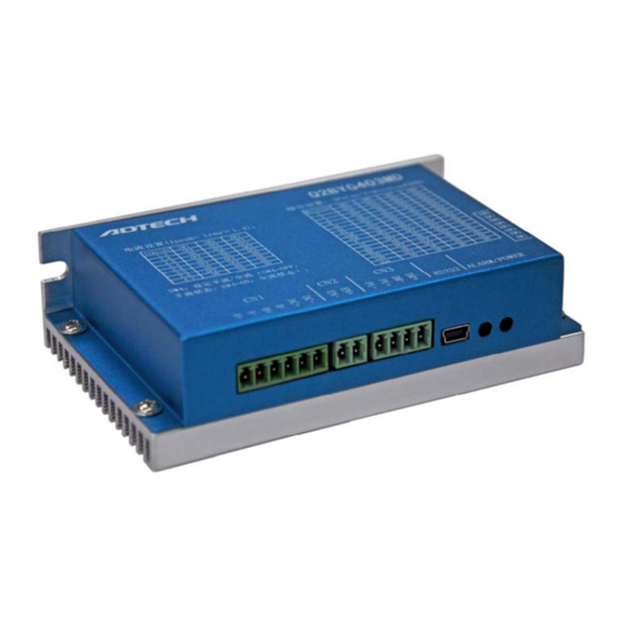
Chapter II. Product Overview 2.1 Introduction Q2BYG403MD is a two-phase digital hybrid step motor Driver basing on AC servo control. It is a new generation digital step motor Driver that integrates advanced DSP control chip and unique control circuit. This design can increase the integrity significantly, and reduce the size and weight. -
Page 5: Chapter Iii. Product Parameters And Installation
Q2BYG403MD Driver User’s Manual vibration, low noise and high-speed. Chapter III. Product Parameters and Installation 3.1 Parameters Table 1: Electrical Parameters Table Parameter Description Input voltage Single power supply 24V~40VDC Overvoltage 45VDC protection point Undervoltage 18VDC protection point Phase current 1.2, 1.6, 2.0, 2.4, 2.8, 3.0, 3.6, 4.2... - Page 6 Q2BYG403MD Driver User’s Manual 3.2 Port description (1) Description of control signal interfaces Signal Function Description High/low voltage level state; requirement: low voltage level 0~0.5V, high voltage level 4~5V, corresponding to two directions of Direction the motor The initial running direction of...
- Page 7 Q2BYG403MD Driver User’s Manual (3) RS-232 communication interface Allow connecting to PC serial port through dedicated cable, modify and save parameters, and monitor the running status through dedicated upper computer commissioning software. PIN No. Name Symbol Application power The internal power supply of the...
- Page 8 Q2BYG403MD Driver User’s Manual 3.3 Installation and wiring diagram 3.3.1 Machine installation size (mm) 3.3.2 Connecting control wires This Driver adopts differential interface circuit, builds in high-speed optocoupler, the receiving frequency is higher than similar products, interface is highly compatible, and anti-jamming capacity is strong (especially differential output mode), and is applicable to NPN open-collector output, PNP type output and differential mode output.
- Page 9 Q2BYG403MD Driver User’s Manual (1) Common anode wiring: when VCC is connected to +5V, R is short connected; when VCC is connected to +12V, R is 1KΩ; when VCC is connected to +24V, R is 2KΩ; (2) Common cathode wiring: when VCC is connected to +5V, R is short connected;...
- Page 10 Q2BYG403MD Driver User’s Manual connected to +24V, R is 2KΩ; Controller Driver PUL+ 200欧 PUL- DIR+ 200欧 DIR- 200欧 3.3.3 Control signal timing diagram To avoid malfunction and deviation, PU, DR and EN signals should meet certain timing requirement, as shown below: 3.3.4 Motor connection...
- Page 11 Q2BYG403MD Driver User’s Manual current value is high, the heating of the Driver and motor will be serious. Therefore, the user needs to select appropriate connection accordingly to get desired effect. The following wiring modes are available. 1.4-wire motor connection 2.6-wire serial connection...
- Page 12 Driver due to short circuit. 3.5 DIP switch setting Q2BYG403MD step Driver uses 8-bit DIP switch to set the output current, subdivision precision, quiescent current and self-tuning of parameters. The front view of DIP switch is shown below: Fig.
- Page 13 Q2BYG403MD Driver User’s Manual (1) Current setting (Ipeak= Irms×1.4): Irms(A) (2) Subdivision setting: Subdivisions (3) Quiescent half current setting Set half/full current (SW4=OFF: half current; SW4=ON: full current). For self tuning setting of parameters, move the SW4 switch once in two seconds to realize the self tuning of motor parameter and Driver parameter.
- Page 14 Q2BYG403MD Driver User’s Manual Chapter IV. FAQ 4.1 Motor selection Q2BYG403MD is suitable for 4, 6, 8-wire two phase hybrid step motor. However, to make the motor have optimized running effect, it is usually required to select appropriate motor to match the Driver.
-
Page 15: Troubleshooting
Q2BYG403MD Driver User’s Manual 4.3 Troubleshooting Failure Possible reason Solution Power supply system Check the power supply circuit Power indicator is has error Supply voltage is low Increase the supply voltage Motor wire isn’t Check the wiring connected properly Alarm indicator is...

Need help?
Do you have a question about the Q2BYG403MD and is the answer not in the manual?
Questions and answers