Advertisement
Quick Links
Screws, washers, etc. at scale 1:1
M4 x 25
Part no. 18
M4 x 8
Part no. 17
M3 x 25
Part no. 6
M3 x 16
Part no. 4
M3 x 12
Part no. 3
M3 x 10
Part no. 57
M3 x 8
Part no. 2
M3 x 6
Part no. 1
M2 x 6
Part no. 114
Countersunk screw M3 x 12
Part no. 65
Tapping screw 2.2 x 4.5
Part no. 21
Nut M4
Part no. 19
Nut M3
---
Nut M2
Part no. 109
Washer 4.3
Part no. 20
Shim 4 x 8 x 1
Part no. 566
Washer 3.2
Part no. 13
Shim 3 x 6 x 0.3
Part no. 1133
Serrated washer 3.2
Part no. 15
Retaining washer 3.2
Part no. 25
Complete list of parts necessary for the assembly (please use EDP-number when ordering spare parts)
Qty.
No.
Assembly part
EDP-No.
Qty.
No.
50
-- Nut M3 ................................
20040
1
44 Link lever ................................
27
1 Screw M3 x 6 ................................
20016
1
46 Frame tail piece ................................
6
2 Screw M3 x 8 ................................
20018
1
47 Bumper, rear ................................
4
3 Screw M3 x 20 ................................
20022
4
52 Rim, grey ................................
8
4 Countersunk screw M3 x 10
20024
5
52 Rim, chromed ................................
13
6 Screw M3 x 25 ................................
20026
9
53 Standard tyre "Ecocontrol ................................
2
11 Screw M3 x 30 ................................
21690
2
57 Screw M3 x 10 ................................
19
13 Washer 3.2 ................................
20046
2
65 Countersunk screw M3 x 12
4
15 Serrated washer 3.2 ................................
20054
2
68 Rear axle ................................
4
17 Hex head screw M4 x 8 ................................
20036
8
70 Spring carrier, plastic ................................
1
18 Hex head screw M4 x 25 20038
1
71 Fifthwheel ................................
1
19 Nut M4 ................................ 20042
1
72 Bar for kingpin ................................
5
20 Washer 4.3 ................................
20048
1
73 Shaft for fifthwheel ................................
1
21 Tapping screw 2.2 x 4.5 ................................
20052
1
74 Draw spring ................................
2
25 Retaining washer 3.2 ................................
20058
16
109 Nut M2 ................................
8
26 Bushing 4 x 0.5 x 7 ................................
20088
16
114 Screw M2 x 6 ................................
1
27 Axle tube ................................
20150
1
179 Carrier plate for kingpin ................................
8
28 Threaded bushing 20mm 20070
1
180 Kingpin stand. fifthwheel 20188
4
32 Spring long, "AF" ................................
20132
2
233 Tool box case ................................
4
33 Spring medium, "AF" ................................
20134
2
234 Tool box cover ................................
4
34 Spring short, "AF" ................................
20136
2
245 Landing leg, yellow ................................
dÉåÉê~ä=åçíÉë=
Please follow the steps of assembly accordingly to the instruc-
tions. Each single assembly step is described and illustrated;
furthermore a parts list indicates the required components for
the actual construction step. Carefully observe the notes ex-
plaining the various steps of assembly and use only those parts
which are provided. This will insure a correct result of assem-
bly.
M3 hex nuts are not provided with an identification number. In-
dividual components in the accessory kits are denoted by a
boldface A in front of the identification number and not in-
cluded in the parts list.
For easier identification of different screws and washers, on the
left side of this page we are adding an illustration of the most
important parts at original scale. Not illustrated parts are to
be identified by comparing the proportion.
Tip: The make-up of this instruction allows putting together
your own booklet if you wish so. For this purpose you have to
fold and stick the pages as follows:
1. Turn round the first page with the English text facing
downwards, and lay the next page on top of the first, with
the English text facing upwards.
2. Glue the two pages together at the left outer edge (e.g. using
adhesive tip) and fold the top page across to the left (with
the fold vertically in the middle).
3. Lay the next page on top of the previous one with the Eng-
lish text facing upwards, stick the left outer edges and fold
over to the left again as before. Similarly add remaining
pages.
4. Finally glue together all pages at the inner edges, too, and
fold the original page over as a cover, sticking it firmly at
the left hand edge.
Assembly part
EDP-No.
Qty.
No.
Assembly part
20148
2
246 Landing leg foot ................................
20002
2
247 Landing leg support ................................
20006
2
248 Crank ................................ 22648
20128
2
341 Blinker lens high, orange 20304
20420
4
342 Lens/rear light, high ................................
28840
4
566 Shim 4 x 8 x 1 ................................
20020
2
709 Lamp cap ................................
20032
2
715 Mudguard support "X" ................................
20126
2
716 Mudguard support "O" ................................
20138
2
717 Mud flap ................................
20008
1
726 Wing nut M4 ................................
20010
1
1090 Frame Gooseneck Dolly ................................
20012
1
1091 Connecting panel ................................
20462
1
1092 Mounting panel, front ................................
21208
2
1093 Crosshead,
21268
Gooseneck Dolly................................
20186
2
1094 Twin-axle fender,
checker plate ................................
21360
1
1133 Shim 3 x 6 x 0.3 ................................
21362
2
1307 Reinforcement panel ................................
23076
WEDICO
®
B-270-4
EDP-No.
22646
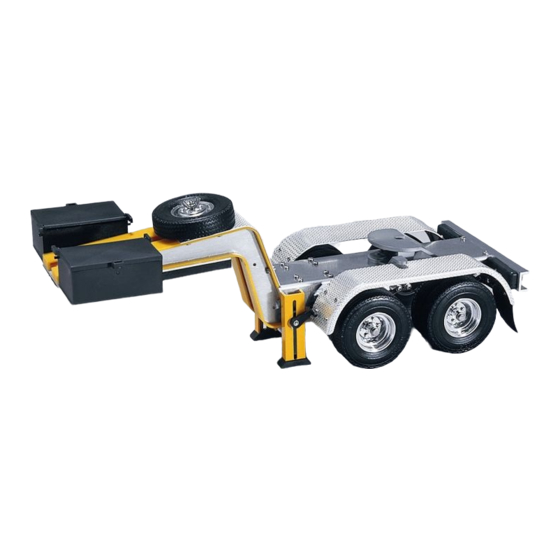
qÉÅÜåáÅ~ä=ÇÉëÅêáéíáçå=
22650
1 to 2mm thick aluminium panels. Stainless steel
Body
threaded connectors and bending wire components,
20308
high impact plastic components.
21998
All individual parts are screwed. All models may be
20264
dismounted and reassembled again.
21275
21274
Measure-
Length over all ..................................... 439 mm
24074
Width over all ....................................... 160 mm
ments:
22906
Height .................................................. 125 mm
27784
27786
27788
27790
24932
25620
27910
dççëÉåÉÅâ=açääó
dççëÉåÉÅâ=açääó
dççëÉåÉÅâ=açääó
dççëÉåÉÅâ=açääó= = = =
270
Art.-No.
Dear modelling enthusiast!
We are glad that you have decided on one of the precious WEDICO
truck models! For the manufacture of individual parts WEDICO uses
durable materials of high quality - rarely to find in these days. This
guarantees durability and enjoyment of your model for years to
come.
If you should ever require replacement parts, please get in touch with
your dealer or directly with WEDICO. For order purpose it is impor-
tant using not only those EDP-numbers mentioned within the general
parts list but also indicating the necessary details concerning colour,
quantity and exact term of the spares required. You may be assured
that WEDICO will supply the replacement part as quick as possible.
Enjoy assembling your truck!
Your WEDICO-Team
© 1998 by WEDICO, P.O. Box 20 04 18, D - 42 204 Wuppertal, Germany.
We can assume no liability for technical or typographical errors.
We reserve the right to incorporate technical modifications.
Duplication and reproduction only with our express consent.
Page 1
270
es1.DOC / FG
09.04.01
Advertisement

Related Manuals for WEDICO Gooseneck Dolly

Summary of Contents for WEDICO Gooseneck Dolly
- Page 1 28 Threaded bushing 20mm 20070 180 Kingpin stand. fifthwheel 20188 checker plate ........ 24932 © 1998 by WEDICO, P.O. Box 20 04 18, D - 42 204 Wuppertal, Germany. 32 Spring long, “AF“ ........ 20132 233 Tool box case ........
- Page 2 71 Standard fifthwheel 1091 Connecting panel 1133 72 Bar for kingpin 1092 Mounting panel, front 73 Shaft for fifthwheel 1093 Crosshead Gooseneck Dolly 74 Draw spring 1133 Shim 3 x 6 x 0.3 A643 1090 Frame Gooseneck Dolly 1307 Reinforcement panel...
- Page 3 Completion of assembly groups dççëÉåÉÅâ=açääó= Assembly of the axles Mounting the rear axle Attach the mud guard support 715 marked "X" onto the right-hand side, and the other mud guard support 716 marked by "O" on the left-hand side. Use screws 6, serrated washers 15, bushing 26, two washers 13 and M3 nuts to fix the supports onto to the rear- ward holes on the frame, provided for the at-...
- Page 4 Completion of assembly groups dççëÉåÉÅâ=açääó= ^ëëÉãÄäó== ^ëëÉãÄäó== çÑ=íÜÉ=Ñêçåí=é~êíë= çÑ=íÜÉ=êÉ~ê=é~êíë= (4 pieces) Assembly step 4 Note! Qty. No. Assembly part Mounting the landing leg Mounting the fenders -- Nut M3 The kit contains two Press one each landing leg foot 246 under Onto the front and rear premounted mud- 1 Screw M3 x 6 additional red lenses 342...
Need help?
Do you have a question about the Gooseneck Dolly and is the answer not in the manual?
Questions and answers