Advertisement
Quick Links
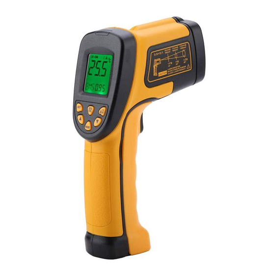
Non-contact infrared thermometer
Instruction manual
Quick start instruction
E
F
HOLD
SCAN
G
(Figure1)
H
DATA
I
LCD display:
A measuring reading
B measuring unit
G data hold icon
C laser on icon
H mode indicator
D back light on icon
I data storge / read icon
E battery power icon
J low temperature alarm icon
F scanning icon
K hight temperature alarm icon
Red laser point
detection hole
(Figure 3)
Attention:
Red laser point only position the general direction the
detection hole is the main parts measure the temperature
2. Locating a hot spot: To find a hot spot aim the
thermometer outside the area of interest, then
scan across with up and down motions unitl you
locate the hot spot.(please turn on the laserto for
accurate measuring)
3. Diagram description
(1) Trigger: When turn on LCD display VER XX
software version for 1 sec. And turn to di-splay
reading with SCAN icon. Release the trigger,
display reading with HOLD icon for 7 sec. Built
in auto power off in 30sec.
(2) Laser / back light button: when back light turn
Introduction
Compact, rugged and easy to use. Just aim and push
the button, read current surface te-mperatures in
AS842A
less than a second. Safely me-asure surface
MODEL:
AS852B
temperatures of hot, hazardo-us or hard-to-reach
AS862A
objects without contact.
How it works
Infrared thermometer measure the surface temperature
of an object. The units optical system sense the object s
emitted energy with different wavelength.It is collected
and focus onto a detector. The unit s electronics system
translated the information into a temperature reading
which is displayed on the unit.
Cautions
Infrared thermometer should be protected for the
following:
--EMF (electro-magnetic fields) from arc weld-ers,
induction heaters.
--Thermal shock (cause by large or abrupt ambi-ent
temperature changes allow 30 minutes for unit to
stabilize before use).
--Do not leave the unit on or near objects of high
temperature.
Warning
Do not point laser directly at eye or indire-ctly off
reflective surfaces.
on , any operations will remain back lig-ht for
D
C
10 sec. LCD indicate on/off status.
F
B
C
A
4
LOW
HIGH
K
J
5
(3)—(6) key functions: press 3 key, LCD subdis-
play blinks MAX-MIN-DIF-AVG-HAL-LAL-
STO segment(only main display means normal
measuring mode) press 4 key to enter.
a. MAX: measuring maximum temperature
b. MIN: measuring minimum temperature
c. DIF: Basic on the reading before press 4 key,
compute the difference of current reading.
d. AVG: measuring average temperature
e. HAL: high temperature alarm--when selected
HAL, press 5 keys to set high temperature alarm
trigger and confirmed by pressing 4 key. When
reading over trigger, LCD display HI icon with
BiBi audio sounds.
f. LAL: low temperature alarm--when selected
LAL, press 5 keys to set low temperature alarm
trigger and confirmed by pressing 4 key. When
reading over trigger, LCD display LOW icon with
BiBi audio sounds
g. STO: data storage--when selected STO, lock &
DATA & 1---indicator will shown when press 4 key.
After temperature read out press 6 key to store,
then 2---memory unit will be shown. There 12
groups memory unit available. To recall the stored
data in normal measuring mode by press-ing 6 key,
remove all data by pressing 6 keys for 2 secretary.
,
7
6
2
8
LASER
SET
STO/CAL
BACKLIT
1
MODE
5
9
3
(Figure3)
(Figure4)
1.When take measurement, point thermome-ter toward
the object to be measured and hold the yellow trigger.
The object under test should be larger than the spot
size cal-culated by the field of view diagram.
2.Distance & spot size: As the distance from the object
increase, the spot size of meas-uring area becomes
larger.
38mm@
D:S=12:1
300mm
1.5 @
12
3. Field of view: Make sure the target is larger than the
,
unit's spot size. The smaller the tar-get the closer
measure distance. When acc-uracy is critical, make
sure the target is at least twice as large as the spot size.
4. Emissivity: Most organic materials and pa-inted or
oxidized surfaces have an emissiv-ity of 0.95 (pre-
set in the unit). Inaccurate readings will result from
measuring shiny or polished metal surfaces. To
compensate, cover the surface to be measured with
mas-king tape or flat black paint. Measure the tape or
painted surface when the tape or painted reach the
same temperature as the material underneath.
Emissivity
Marterial
Aluminum
0.30
Asbestos
0.95
Asphalt
0.95
Basalt
0.70
Brass
0.50
Brick
0.90
Carbon
0.85
Ceramic
0.95
Concrete
0.95
Copper
0.95
Dirt
0.94
Frozen food
0.90
Hot food
0.93
Glass(plate)
0.85
Ice
0.98
h. EMS: Emissivity setup--press 5 keys for emissivity
settings, press 4 key to save setup and back to
normal status.
(7) LCD
(8) Battery door clip
(9) Battery door: When replace battery door, please
press battery door clip and pull the battery door.
(10) Clesius / Fahrenheit switch: Please open battery
and push the slide switch for con-vertsion
Maintenance
1) Lens cleaning: Blow off lose particles using
clean compressed air. Gently brush remaining
debris away with a moist cotton cloth.
2) Case cleaning: Clean the case with a damp
sponge/cloth and mild soap.
Note:
1) Do not use solvent to clean lens.
2) Do not submerge the unit in water.
Specifications
AS842A
Temperature
-50℃~600℃
range
-58℉~1112℉
100℃(212℉) to 600℃(1112℉)±2℃or±2%
0℃(32℉) to 100℃(212℉) ±2℃or±2%
Accuracy
-50℃(-58℉)to 0℃(30℉) ±3℃or ±3%
whichever is greater
Repeatability
1% of reading or 1℃
Response time
500 mSec, 95% response
Spectral response
8-14 um
Emissivity
0.10 to 1.00 adjustable (pre-set 0.95)
Ambient operating
0 ~40℃ (32 ~ 104℉)
range
Relative humidity
10-95% RH noncondensing
Storage temperature
-20 to 60℃ (-4 to 140℉) without battery
Weight/Dimensions
170G ; 175*100*49mm
9v Alkaline or NiCd battery
Power
Battery life (Alkaline)
Laser Models:12 hrs
Distance to Spot Size
12:1
75mm@
132mm@
900mm
1500mm
3.0 @
5.3 @
60
36
Emissivity
Marterial
Iron
0.70
Lead
0.50
Limestone
0.98
Oil
0.94
Paint
0.93
Paper
0.95
Plastic
0.95
Rubber
0.95
Sand
0.90
Skin
0.98
Snow
0.90
Steel
0.80
Textiles
0.94
Water
0.93
Wood
0.94
AS852B
AS862A
-50℃~750℃
-50℃~900℃
-58℉~1382℉
-58℉~1652℉
Advertisement

Subscribe to Our Youtube Channel
Related Manuals for Smart Sensor AS842A


Summary of Contents for Smart Sensor AS842A
- Page 1 Compact, rugged and easy to use. Just aim and push the object to be measured and hold the yellow trigger. the button, read current surface te-mperatures in The object under test should be larger than the spot AS842A less than a second. Safely me-asure surface MODEL: AS852B size cal-culated by the field of view diagram.
- Page 2 The object under test should be larger than the spot AS842A less than a second. Safely me-asure surface size cal-culated by the field of view diagram.
- Page 3 (3)—(6) key functions: press 3 key, LCD subdis- 2) Do not submerge the unit in water. Red laser point play blinks MAX-MIN-DIF-AVG-HAL-LAL- STO segment(only main display means normal Specifications AS842A AS852B AS862A measuring mode) press 4 key to enter. Temperature -50℃~600℃...
Need help?
Do you have a question about the AS842A and is the answer not in the manual?
Questions and answers