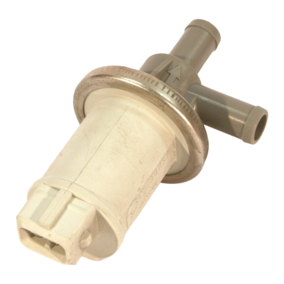
Summary of Contents for KMS Idle control kit
- Page 1 EN—NL—DE kms.vankronenburg.nl Idle control kit Manual for installation, setup and calibration • Handleiding voor installatie, instelling en kalibratie • Anleitung für Installation, Setup und Kalibration •...
- Page 3 EN—NL—DE kms.vankronenburg.nl Idle control kit Part nr: 01-01-01-0008 Technical specifications and installation...
- Page 4 EN—NL—DE kms.vankronenburg.nl This document contains detailed information about the KMS Idle control kit. Ad- ditional information, user manuals, wiring examples ands software can be found on our website: kms.vankronenburg.nl or on the software CD included with the ECU. Contents of the package •...
- Page 5 EN—NL—DE kms.vankronenburg.nl The idle-solenoid needs +12 Volt on one pin and a signal from the KMS management on the other pin. You can change the polarity without influencing the functioning of the valve. To connect/wire the idle-control valve to the KMS ECU’s, use pin numbers 4 (MD35 only), 6, 22, 23 or 24 (MP25 only, see next page).
- Page 6 Software setup for KMS MP25 ECU When using a KMS MP25 ECU, the idle control valve must be defined in the hard- ware configuration of the ECU. In the main screen of the KMS ECU software pro- gram, go to ‘options (F4)’ and then click ‘hardware configuration’. Here you can enable the idle control and define the pin to which the idle control valve is con- nected.
-
Page 7: Fault Tracing
- No 12 volt supply not activate on the idle control valve - Hardware configuration not set to the right out- - Change the KMS ECU put PIN Hardware configurations - Parameters not set - Check the setup of the... - Page 8 EN—NL—DE kms.vankronenburg.nl Stationair regeling kit Onderdeel nr: 01-01-01-0008 Technische specificaties en installatie...
- Page 9 EN—NL—DE kms.vankronenburg.nl Dit document bevat gedetailleerde informatie over de KMS stationair regeling. Overige informatie, handleidingen, kabelboomschema’s en software kan worden gevonden op onze website: kms.vankronenburg.nl of op de software CD bijgele- verd bij deze ECU. Inhoud van de kit •...
- Page 10 EN—NL—DE kms.vankronenburg.nl De stationair-solenoid heeft +12 Volt nodig op één pin en een signal van de KMS ECU op de andere pin. Deze pinnen kunnen zonder problemen worden omgedraaid (de polariteit heeft geen invloed). Om de stationair klep aan te sluiten op de KMS ECU’s, gebruik pin nummers 4 (alleen MD35), 6, 22, 23 of 24 (alleen MP25, info volgende hoofdstuk).
- Page 11 Software instelling voor de KMS MP25 ECU Wanneer er gebruik wordt gemaakt van een KMS MP25 ECU, moet de stationair regelklep in de software worden gedefineerd. Open hiervoor de KMS ECU soft- ware, ga naar ‘options (F4)’ en vervolgens naar ’Hardware configuration’. Hier kan de stationairregeling onder ‘Idle control output’...
- Page 12 - Controleer voeding van - Geen 12V voeding wordt niet geactiveerd stationair regelklep - Hardware configuratie niet op juiste ingangpin - Wijzig de KMS ECU ingesteld Hardware configuratie - Parameters in de sta- - Controleer de in- tionair afstelling (F6 in...
- Page 13 EN—NL—DE kms.vankronenburg.nl Leerlauf Kit Teilenummer: 01-01-01-0008 Technische Information und Einstellung...
- Page 14 EN—NL—DE kms.vankronenburg.nl Dieses Dokument enthält detaillierte Information über den KMS Leerlauf Kit. Weitere Informationen, Bedienungsanleitungen, Schaltpläne finden Sie auf unse- rer Website: kms.vankronenburg.nl oder auf die bei dem Steuergerät beigeleg- ten CD. Inhalt von diesem Kit • Leerlaufventil (idle control valve) •...
- Page 15 Die Polarität hat keinen Einfluß auf die Wirkung vom Ventil. Der Ausgang am KMS MD35 Steuergerät ist auf Position 4 und für MP25 die Posi- tionen 6, 22, 23 oder 24 (Siehe nächstes Kapitel). Ausführliche Schaltpläne sind auf unsere website zu finden.
- Page 16 Software setup für KMS MP25 ECU Wenn ein KMS MP25 ECU verwendet wird, muβ das Leerlaufventil zugewiesen werden in die 'Hardware Configuration' vom Steuergerät. Wenn Sie sich im Haupt- schirm von der Software befinden gehen Sie zu 'Options (F4)' und dann 'Hardware Configuration'.
-
Page 17: Fehlersuche
- überprüfen Sie die Wärte - Die Wärte für den Leer- in die 'Idle control tables lauf sind nicht richtig (F6). eigegeben (Idle control tables(F6) in der KMS management software). Die Leerlaufregelung - Drosselklappe zu weit - überprüfen Sie wie der funktioniert nicht motor läuft ohne Leerlau-... - Page 20 Please visit our website for more information, manuals, software and prices: kms.vankronenburg.nl...


Need help?
Do you have a question about the Idle control kit and is the answer not in the manual?
Questions and answers