Advertisement
Quick Links
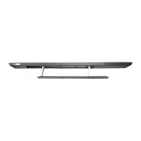
Made in the USA
Newest features:
40% stronger (tougher) with use of high strength materials (carbon steel).
•
All new Smart Motor for improved, consistent motion. Intelligent acceleration and
•
deceleration provides quiet, smooth operation.
Updated harness for simplified, quicker installation.
•
Improved mechanical components increase reliability and reduce maintenance (warranty).
•
To watch a installation video on
our step slider, scan the QR code
and scroll down on the page.
ROCKSLIDEENGINEERING.COM
INSTALLATION MANUAL
GEN 3 STEP SLIDER JT 2019-PRESENT
- NEED ASSISTANCE? 435.752.4580 - PAGE 1
BD-SS-300-JT4
REVISED 4/7/2021
Advertisement

Related Manuals for ROCKSLIDE BD-SS-300-JT4


Summary of Contents for ROCKSLIDE BD-SS-300-JT4
- Page 1 INSTALLATION MANUAL GEN 3 STEP SLIDER JT 2019-PRESENT BD-SS-300-JT4 Made in the USA Newest features: 40% stronger (tougher) with use of high strength materials (carbon steel). • All new Smart Motor for improved, consistent motion. Intelligent acceleration and • deceleration provides quiet, smooth operation.
-
Page 2: Parts List
Parts List Front Bracket Description Quantity Electric Step Slider (Pair) Bump stop plate with VHB backing Wiring harness VHB Backed Sensors Magnets Alcohol wipes Middle Bracket Rocker cutoff switch 5/16” - 18 nylock nut 5/16” - SAE yellow zinc washer 1/4”... - Page 3 Step 1 REMOVE THE FUSE FROM THE HARNESS. Attach the wire cable holder and gold flange bolt halfway down the red/black battery wires and into the hole shown. Do not tighten down at this moment. Run the red wire with fuse holder and black wiring loom from the rear pas- senger door along the frame, through the wheel well area along the frame,...
- Page 4 Step 3 With the wires attached to the battery, secure this section of the harness down to the golden bolt with wire clip leav- ing just a little bit of slack between the battery and gold bolt to allow wiring to be a little slack.
- Page 5 Step 6 Remove the silver covering that hides the plug (if applicable), and then pop the plug out from below using a punch or screwdriver and a hammer to hit it up and out. Run the door sensors up through this hole, run the grommet over the sensor plugs and down the wiring to install in the hole.
- Page 6 Step 7.1 Door Sensor Location The JT will have a different location for the sensors on the rear vs the JL. On the front door, mount the sensor below the latch as show as long as the wires run towards the inside of the vehicle.
- Page 7 Continue External Harness install—Step 8 Pull the harness from the passenger side to the driver side by running the rest of the harness up over the crossmem- ber and secure it with zip ties to the crossmember. Step 9 Pop the panels on the driver side. Remove the silver cov- ering (if applicable) and pop the plug out as you did on the passenger side.
- Page 8 Mechanic Install—Step 10 **IF INSTALLED, REMOVE FACTO- RY SLIDERS* Start on the drivers side. Remove two front pinch seam bolts on the lower front corner panel fender using a 10mm socket and wrench. Leave the holes open. Keep the hardware as you will re-install it in the final step Step 11 Starting on the driver side, locate the...
- Page 9 Step 14 – Bump Strap Install Install bump strap onto the side of the vehicle where the bend just under the door is located: Clean the area to be fitted with an alco- hol wipe. Test fit the bumper strap by lining up the strap straight across the jeep bend.
- Page 10 Step 16 Pull the motor wire out from the hos- ing and slide it though the little cutout between the last bolt and step slider bracket mounting hole and plug into the main harness. Pull the circuit board plug through the hole and plug into the sealed circuit board.
- Page 11 Step 18 Install 12 5/16” - 18 x 1” with a hex head bolts with yellow SAE washers into the bracket through the slots on the underside of the step slider. Install bolts halfway. **If you purchased the optional skid plate, install at this time using those same bolts.
- Page 12 Step 21—Install Master Switch Bracket Remove the OBD2 port screw using an 8mm socket. Insert screw through large hole on the master switch bracket, and then back through the OBD2 port bracket, and install back into place to hand tight. Install ground wire between the bolt and OBD2 plate.
- Page 13 TROUBLESHOOTING YOUR STEP SLIDERS: I just installed my steps and they are Double check the connections. Check the fuse to make sure it is plugged in. Is the on / off not coming down when I open the door. switch getting power? Is the circuit board plugged in? Are the door sensors plugged in? My switch is getting power, but The light is only supposed to be on when the system is turned on.
-
Page 14: Warranty Policy
WARRANTY POLICY ROCK SLIDE ENGINEERING, LLC (RSE) covers a limited warranty ensuring the structure is free of material de- fects and workmanship, under proper installation and normal use/conditions. Additionally, the electrical components (including the motor) and the finish (powder coat) will be free of defect for a period of (12) months (1) year from the original purchase date. - Page 15 GENERAL MAINTENENCE MANUAL Made in the USA To ensure your step sliders function properly, some maintenance is required! You will need to lubricate the pivot points that are circled in red shown above. Lubricate the heim joints and aluminum blocks as shown below. We recommend you do it monthly or after any off-road adventure, including during winter months.
Need help?
Do you have a question about the BD-SS-300-JT4 and is the answer not in the manual?
Questions and answers