
Related Manuals for Equalizer International SG13TE


Summary of Contents for Equalizer International SG13TE
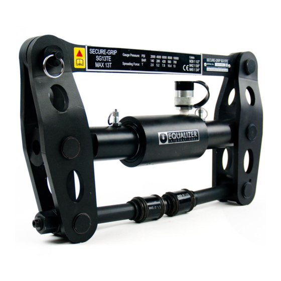
- Page 1 SG13TE, SG15TE SECURE-GRIP HYDRAULIC FLANGE SPREADERS Operator Instruction Manual info@equalizerinternational.com www.equalizerinternational.com INNOVATION IN ITS MOST FUNCTIONAL FORM...
-
Page 3: Table Of Contents
The Equalizer Secure-Grip Flange Spreading Tools are a range of tools designed to assist in access gap producing a spreading force of up to: 26T (260kN) for the SG13TE when used in pairs 30T (300kN) for the SG15TE when used in pairs... -
Page 4: Safety Information
Only people competent in the use of hydraulic equipment should use these tools. operator, and when present, any assisting personnel, is of paramount importance along with These instructions are only to cover the safe operation of THE EQUALIZER SG13TE & SG15TE SECURE-GRIP HYDRAULIC TOOLS during normal maintenance/installation operations. All oth-... - Page 5 A CAUTION is used to indicate correct operating or maintenance procedures and practices to prevent damage to, or destruction of equipment or other property. A WARNING indicates a potential danger that requires correct procedures or practices to avoid personal injury. A DANGER is only used when your action or lack of action may cause serious injury or even death.
-
Page 6: Kit Components
3. KIT COMPONENTS SG13TE KIT COMPONENTS 1 x SG13TE Tool c/w Hydraulic Cylinder with Gauge 1 x Safety Block 1 x Instruction Manual 1 x Carry-Case with Protective Foam Inserts Product Code: SG13TESTD SG15TE KIT COMPONENTS 1 x SG15TE Tool c/w Hydraulic Cylinder... -
Page 7: Technical Data
4. TECHNICAL DATA SG13TE TECHNICAL DATA Spreading force = 13 T (130 kN) per tool Pressure 2000 4000 6000 8000 10,000 10.4 Spreading force Spreading distance = 0 - 115mm (0 - 4.53”) SG15TE TECHNICAL DATA Spreading force = 15 T (150 kN) per tool... -
Page 8: How The Secure-Grip Hydraulic Tools Work
5. HOW THE SECURE-GRIP HYDRAULIC TOOLS WORK The two halves of the hydraulic Secure-Grip tool are inserted into Both drive nuts are tightened locking are locked into position The hydraulic hose and hand pump are attached The hand pump is actuated which powers the hydraulics that spread the SECURE-GRIP HYDRAULIC FLANGE SPREADERS PAGE 6... -
Page 9: Installation And Operation
Collet type Minimum Maximum Metric coarse UNC bolt Tool bolt-hole bolt-hole bolt diameter diameter M39 1 ½” SG13TE SG13TE M45 1 ¾” SG13TE 47.5 SG15TE M52 2” 50.5 SG15TE M56 2 ¼” 55.5 SG15TE To increase the lifespan of the collets it is recommended that they are See section 6.3 for details on collet removal and replacement... -
Page 10: Collet Selection Based On Bolt-Hole Measurment
6.2 COLLET SELECTION BASED ON BOLT-HOLE MEASUREMENT Note: It is important that the vernier calliper is held in the middle of the hole which is worn, damaged or distorted, as these actions may result in the selection of an incorrect size of collet To ensure a true measurement is taken, hold the vernier calliper: SECURE-GRIP HYDRAULIC FLANGE SPREADERS PAGE 8... - Page 11 To read the measurement from the vernier calliper, scan along the desired scale from left to right. In 60mm, this is added to the minor the vernier scale aligns with the measurement of 68mm. operator can determine which collet and tool is appropriate to this MAJOR MINOR FIGURE...
- Page 12 Each tool in the Secure-Grip range comes with the appropriate sizes of collets for that - slide the collet over the collet holder - measure the centre section of the collet with the vernier calliper Centre Collet type Min. Max. Metric coarse UNC bolt section Ø...
-
Page 13: Collet Removal And Replacement
6.3 COLLET REMOVAL AND REPLACEMENT Place the tool on its side on a work and remove the drive nut DRIVE Pull the collet spring plunger ring out, and remove the collet head COLLET SPRING PLUNGER RING DRIVE CONE and drive cone off the collet DRIVE TUBE holder COLLET... -
Page 14: Standard Installation And Operation
6.4 STANDARD INSTALLATION AND OPERATION Before attaching the tool ensure at least degrees apart with nuts loosened spreading. parts Pull the cantilever pin out and rotate the cantilever out of position. CANTILEVER CANTILEVER ACTUATOR Pull on the left hand actuator spring ACTUATOR TO LEG plunger and pull the actuator from... - Page 15 LOCKING SCREW using the vernier calliper DEPTH provided. Lock the calliper in GAUGE screw to attach the tool. Insert the depth gauge part of the BOLTING FACE the tool into the the opposite end of COLLET that the collet is fully through one DRIVE Tighten the drive nut with the DRIVE FLEXIBLE...
- Page 16 Insert the collet on the second half the tool, and tighten the drive nut handle. The second half of the tool will now have a secure hold in the ACTUATOR SPRING Insert one side of the actuator into PLUNGER ACTUATOR each ‘actuator to leg connector’.
- Page 17 the tool you have just attached and repeat steps 2 to 7 for the second tool Note: If more than attached at an equal spacing around the ACTUATOR HYDRAULIC Connect the hand pumps to the HOSE hydraulic hoses, and the HAND PUMP hydraulic hoses to the actuators on each tool.
- Page 18 SG13TE SG15TE to section 10 MAX. Pressure 2000 4000 6000 8000 10,000 SG13TE spreading force 10.4 SG15TE spreading force SAFETY BLOCK FLANGE and prior to any maintenance BOLT Following any maintenance works RELEASE VALVE...
-
Page 19: Restricted Access Installation And Operation
6.5 RESTRICTED ACCESS INSTALLATION AND OPERATION COLLET HEAD DRIVE ASSEMBLY On one half of the tool unscrew and remove the drive nut. Pull the collet spring plunger ring out, and remove the collet head COLLET SPRING PLUNGER open access side RESTRICTED ACCESS holder... -
Page 20: Valve, Spade Or Blind Removal Installation And Operation
6.6 VALVE,SPADE OR BLIND REMOVAL, INSTALLATION AND OPERATION valves. Equalizer International can supply a short collet holder kit that will increase the relative stroke of the tool. TOOL collet holder C min C Max SG13TE standard SG13TE short SG15TE standard... -
Page 21: Maintenance And Lubrication
7. MAINTENANCE AND LUBRICATION surface Remove the cantilever pin and CANTILEVER CANTILEVER RETAINING RING remove the collet union, actuator connector and ACTUATOR CONNECTOR cantilever retaining rings. Care RETAINING RING COLLET UNION the retaining rings during removal RETAINING RING or replacement the tool the cantilever from the tool CANTILEVER... - Page 22 The exposed parts of the tool can CENTRING SPRINGS GREASE centring springs do not jump out of their recess Note: it is recommended that the tool is wiped down with a clean rag DOWEL procedure taken to ensure the dowel protruding from the right hand leg of the tool is engaged centering springs...
-
Page 23: Parts Lists
8. PARTS LISTS SG13TE PARTS LIST ITEM PART NO. DESCRIPTION QUANTITY 641301-10 LEG RETAINING RING 641101-04 LEG 900502-02 M10 SPRING PLUNGER 641501-01 CANTILEVER 641901-02 ACTUATOR UNION 641401-02 ACTUATOR PIN 641701-01 PULL PIN SEE COLLET HEAD PARTS LIST 643201-01 CANTILEVER PIN... - Page 24 SG15TE PARTS LIST ITEM PART NO. DESCRIPTION QUANTITY 641301-10 LEG RETAINING RING 651101-04 LEG 900502-02 M10 SPRING PLUNGER 651501-01 CANTILEVER 651901-02 ACTUATOR UNION 651401-02 ACTUATOR PIN 641701-01 PULL PIN SEE COLLET HEAD PARTS LIST 643201-01 CANTILEVER PIN 644001-01 ACTUATOR ASSEMBLY COLLET HEAD PARTS LIST ITEM PART NO.
- Page 25 HP550S PARTS LIST PUMP PUMP ITEM PART No. DESCRIPTION ITEM PART No. DESCRIPTION QUANTITY QUANTITY QUANTITY QUANTITY 710101-01 PUMP HOUSING 716300-01 SERVICE KIT M: - GAUGE COUPLER 730601-01 RESERVOIR FEMALE 715300-01 SERVICE KIT C: - COUPLER - O-RING - PORT GAUGE - BACK-UP RING - H.P.
-
Page 26: Weights And Dimensions
9. WEIGHTS AND DIMENSIONS CLOSED TOOL DIMENSIONS OPEN TOOL DIMENSIONS TOOL TOOL WEIGHT WEIGHT SG13TE SG15TE SECURE-GRIP HYDRAULIC FLANGE SPREADERS PAGE 24 OPERATOR INSTRUCTION MANUAL... -
Page 27: Troubleshooting
10. TROUBLESHOOTING The release valve is in the retract Close the release valve CLOSE RELEASE VALVE One or more of the connectors are Check all connectors are fully tightened and the release valve is in the not fully tightened and the fully closed position hydraulic oil cannot pass through from the pump to the cylinder... - Page 28 minimal and feels spongy xxxxxxxxx Use the airlock removal the hydraulic system procedure as follows: OPEN RELEASE Connect the hand pump to the VALVE tool with the hydraulic hose Close the release valve on the pump, and prime the pump until the hydraulic cylinder is fully extended and a small pressure is achieved...
- Page 29 A collet which is too selected, or the collet a damaged or non- 1. Pull the collet spring plunger ring out, and remove the rest of the tool, leaving the 2. Unscrew the drive nut and remove the drive cone and collet cone onto the collet holder until it is 1-2mm off the end...
- Page 30 A collet which is too selected, or the collet achieved as follows: a damaged or non- spring plunger ring out, and remove the rest of the tool, leaving the collet head drive nut and remove the drive cone and collet cone 3.
-
Page 31: Secure-Grip Tool Range
SG4TM manual 17.5 19.5 SG4TM manual 20.5 SG6TM manual 26.5 SG6TM manual 27.5 SG11TM manual SG11TM manual SG11TM manual SG13TE hydraulic SG13TE hydraulic SG13TE hydraulic SG15TE hydraulic 47.5 SG15TE hydraulic 50.5 SG15TE hydraulic 55.5 SG18TE in-line hydraulic 59.5 SG18TE in-line hydraulic... -
Page 32: Range Of Application Charts
12. RANGE OF APPLICATION CHARTS see page 29 ANSI compact see page 30 see page 30 reducing see page 31 see page 32 threaded see page 32 weldneck see page 33 see page 33 lapped see page 33 ASME series A weld neck see page 34 series A lapped see page 35... -
Page 33: Spo
SG4TM SG4TM SG4TM SG6TM SG6TM SG4TM SG4TM SG6TM SG6TM SG11TM SG4TM SG4TM SG6TM SG11TM SG11TM SG4TM SG4TM SG4TM SG6TM SG11TM SG13TE SG4TM SG4TM SG6TM SG11TM SG13TE SG15TE SG4TM SG6TM SG6TM SG11TM SG13TE SG15TE SG4TM SG6TM SG6TM SG11TM SG15TE SG15TE SG4TM... -
Page 34: Ansi Compact
SG4TM SG4TM SG4TM SG4TM SG4TM SG6TM SG4TM SG4TM SG4TM SG6TM SG11TM SG4TM SG4TM SG4TM SG6TM SG11TM SG4TM SG4TM SG6TM SG11TM SG13TE SG4TM SG6TM SG11TM SG11TM SG15TE SG4TM SG6TM SG11TM SG11TM SG13TE SG4TM SG11TM SG11TM SG13TE SG15TE SG6TM SG11TM SG11TM SG13TE... - Page 35 SG6TM SG6TM SG11TM SG4TM SG4TM SG4TM SG4TM SG6TM SG11TM SG11TM SG4TM SG4TM SG6TM SG6TM SG4TM SG4TM SG6TM SG6TM SG11TM SG11TM SG13TE SG4TM SG4TM SG6TM SG6TM SG11TM SG13TE SG13TE SG4TM SG4TM SG6TM SG6TM SG11TM SG11TM SG15TE SG4TM SG6TM SG6TM SG11TM SG11TM...
- Page 36 SG4TM SG6TM SG6TM SG11TM SG11TM SG4TM SG6TM SG6TM SG11TM SG11TM SG6TM SG6TM SG11TM SG11TM SG11TM SG6TM SG6TM SG11TM SG11TM SG13TE SG6TM SG11TM SG11TM SG11TM SG13TE SG6TM SG11TM SG11TM SG13TE SG11TM SG11TM SG13TE DIN threaded Class PN16 PN25 PN40 PN64 PN100...
- Page 37 SG11TM SG11TM SG11TM SG4TM SG6TM SG4TM SG11TM SG11TM SG11TM SG4TM SG6TM SG4TM SG11TM SG11TM SG11TM SG6TM SG6TM SG6TM SG11TM SG11TM SG13TE SG6TM SG6TM SG6TM SG11TM SG13TE SG13TE SG6TM SG11TM SG6TM SG11TM SG13TE SG6TM SG11TM SG6TM SG13TE SG6TM SG11TM SG6TM SG11TM...
-
Page 38: Asme Series A Weld Neck
SG6TM SG6TM SG11TM SG4TM SG4TM SG4TM SG4TM SG6TM SG11TM SG11TM SG4TM SG4TM SG6TM SG6TM SG4TM SG4TM SG6TM SG6TM SG11TM SG11TM SG13TE SG4TM SG4TM SG6TM SG6TM SG11TM SG13TE SG13TE SG4TM SG4TM SG6TM SG6TM SG11TM SG11TM SG15TE SG4TM SG6TM SG6TM SG11TM SG11TM... -
Page 39: Series A Lapped
SG6TM SG6TM SG11TM SG4TM SG4TM SG4TM SG4TM SG6TM SG11TM SG11TM SG4TM SG4TM SG6TM SG6TM SG4TM SG4TM SG6TM SG6TM SG11TM SG11TM SG13TE SG4TM SG4TM SG6TM SG6TM SG11TM SG13TE SG13TE SG4TM SG4TM SG6TM SG6TM SG11TM SG11TM SG15TE SG4TM SG6TM SG6TM SG11TM SG11TM... -
Page 40: Api 6B Weld Neck
SG4TM SG6TM SG6TM SG4TM SG6TM SG6TM SG4TM SG6TM SG11TM SG6TM SG11TM SG11TM SG6TM SG11TM SG13TE SG6TM SG11TM SG11TM SG11TM SG11TM SG13TE SG11TM SG11TM SG15TE Class Nominal collet tool collet tool collet tool pipe size... - Page 41 SECURE-GRIP HYDRAULIC FLANGE SPREADERS PAGE 39 OPERATOR INSTRUCTION MANUAL...
Need help?
Do you have a question about the SG13TE and is the answer not in the manual?
Questions and answers