Table of Contents
Advertisement
Quick Links
Advertisement
Table of Contents

Related Manuals for Vulcan-Hart FC-500VC


Summary of Contents for Vulcan-Hart FC-500VC
- Page 1 PRECISION . ACCURACY USER’S MANUAL FC-500VC...
-
Page 2: Warning
Preface Thank you for choosing a VULCAN FC-500VC. To ensure high cutting quality and optimal productivity, be sure to read this User's Manual thoroughly prior to use. WARNING Manual • No part of this publication may be reproduced, stored in a retrieval system, or transmitted, in any form or by any means, without the prior written permission of VULCAN Corporation. -
Page 3: After Turning On The Cutting Plotter
After Turning on the Cutting Plotter During operations, immediately after completion of operations, and when setting the cutting plotter functions, the carriage, Y bar,will move to the origin position, and other parts which are not fixed, may move suddenly. Do not let your hands, hair, or clothing get too close to the moving parts or within their range of movement. Do not place any foreign objects in or near these areas either. -
Page 4: Table Of Contents
CONTENTS WARNING ..............................1 Manual Cutter Machine Caution Label After Turning on the Cutting Plotter ......................2 About the words and phrases in this text ....................2 Chapter 1: Product Summary 1.1 Machine Specifications ........................6 1.2 Accessories List...........................7 1.3 Product Introduction ...........................8 1.4 Control Panel ............................9 Screen(LCD) Control key Chapter 2: Installation Equipment... - Page 5 3.3 Setting the Origin Point........................22 3.4 Running Cutting Tests ........................23 Test Speed and Force Test Fit 3.5 Stop Cutting .............................24 Normal Stop Abnormal Stop 3.6 Duplicate Cutting ..........................25 3.7 Offline output ............................26 3.8 Setting ............................27-30 Calibrate Cutter Size Offset Calibration Operating Mode About Chapter 4: Troubleshooting and Maintenance...
-
Page 6: Chapter 1: Product Summary
Chapter 1: Product Summary Product Summary 1.1 Machine Specifications 1.2 Accessories List 1.3 Product Introduction 1.4 Control Panel Page 5... - Page 7 Chapter 1: Product Summary 1.1 Machine Specifications Item FC-500VC Digital servo system, Flatbed Configuration Vacuum suction Media hold-down method 700 mm/s (10 to 700 mm/s ) Maximum cutting speed Tool 1: Max. 5.88 N (600 gf) Cutting pressure Tool 2: Max. 5.88 N (600 gf) Minimum character size Approx.
- Page 8 Chapter 1: Product Summary 1.2 Accessories List Accessories for flatbed cutting plotter Ethernet cable x 1pc Power cable x 1pc USB cable x 1pc Creasing tool x 1pc Creasing head x 1pc Blade holder x 1pc Pen calibration tool x 2pcs 30°Blade x 1pc 60°Blade x 1pc Pen x 5pcs...
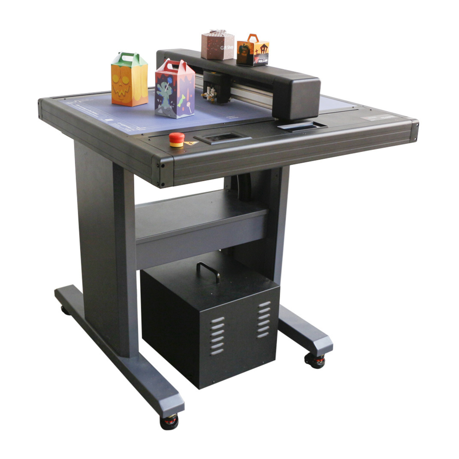
- Page 9 Chapter 1: Product Summary 1.3 Product Introduction (1) Tool carriage ....Part to drive the cutter/pen (2) Y Bar.......Holds the tool carriage; moves left/right (3) Writing panel....Cutting/Plotting/Creasing work is performed on the panel. (4) Storage box....Placing tools such as knives, holders, pen holders, etc. (5) Control panel....Used to access various cutting plotter functions.
-
Page 10: Screen(Lcd)
Chapter 1: Product Summary 1.4 Control Panel Screen (LCD) (1) Acceleration display ..Arrow key speeds for carriage control, Fast (x10) / Slow (x1). (2) Carriage coordinates..The coordinates of carriage on the table. (3) Arrow keys......To move carriage to different positions. (4) Speed......Carriage moving speeds (tool1/tool2) during working. -
Page 11: Chapter 2: Installation Equipment
Chapter 2: Installation Equipment Installation Equipment 2.1 Stand and Cutter installation 2.2 Air pump installation 2.3 Use of tools 2.4 Attaching a tool 2.5 Connecting to the Computer Page 10... - Page 12 Chapter 2: Installation Equipment 2.1 Stand and Cutter installation First,install beams to stand legs, hex screws(8) and hex key be used. Second,install beam cover onto beams, phillip screws(4) and phillip screwdriver be used. Finally, Put machine on floor stand, hex screws(4) and hex key be used. Note:Please check labels on machine and stand, to ensure correct direction and positon.
- Page 13 Chapter 2: Installation Equipment 2.2 Air pump installation The screw pattern of the silencer is very sharp. Wear gloves when installing to prevent caution scratches. Transfer tube 2 The blue tube is for easy installation of the transfer hose. When installing, please unscrew the blue tube. Silencer Air pump Transfer tube 1...
- Page 14 Chapter 2: Installation Equipment Note: The transfer hose need to be passed through beam cover. Page 13...
-
Page 15: Blade Holder
Chapter 2: Installation Equipment 2.3 Use of tools To avoid bodily injury, handle cutter blades with care. caution Blade holder blade holder cap blade holder blade First,unscrew the blade holder cap,as shown. Second,place the blade (as shown) into the slot of the blade seat. Finally, screw the blade holder cap to complete the installation and replacement of the blade. -
Page 16: Pen Holder
Chapter 2: Installation Equipment Pen holder pen holder cap pen holder First,unscrew the Calibration tool cap,as shown. Second,place the pen (as shown) into the slot of the pen seat. Finally, screw the Calibration tool cap to complete the installation and replacement of the pen. Creasing tools Step1,unscrew old creasing head. -
Page 17: Attaching A Tool
Chapter 2: Installation Equipment 2.4 Attaching a tool When pushing the tool holder with your fingers, the blade tip may be protruding. Take care not to cut your fingers. caution When mounting the tool in the tool holder, please note the following. •... -
Page 18: Connecting To The Computer
Chapter 2: Installation Equipment 2.5 Connecting to the Computer Connect the plotter to the computer using the communication cable. Use either the USB interface, network (LAN) interface to connect the plotter to the computer. Select the port depending on the specification of the software to be used and the availability of the interface port on the computer. -
Page 19: Connection Via Power Cable
Chapter 2: Installation Equipment Connection via power cable Supplement When turning off the power, wait over 10 seconds before turning on it again, otherwise problems may occur with the display. Connection via Air pump cable Supplement The vacuum pump is supplied as a standard accessory.No other air pump models are available yet. * The air pump has 2 wires, one needs to be connected to the machine, and the other is connected to the power. -
Page 20: Chapter 3: Convenient Functions
Chapter 3: Convenient Functions Convenient Functions 3.1 Loading the Media 3.2 Move the Tool Carriage 3.3 Setting the Origin Point 3.4 Running Cutting Tests 3.5 Stop Cutting 3.6 Duplicate Cutting 3.7 Offline Output 3.8 Settings Page 19... - Page 21 Chapter 3: Convenient Functions 3.1 Loading the Media Supplement • This plotter is available with a vacuum suction writing panel. • There are media that cannot be held down by vacuum suction. Please test before use. • When loading a media that cannot be securely attached using the vacuum duction, reinforce adhesion by using tape on all four sides.
-
Page 22: Move In Steps Manually
Chapter 3: Convenient Functions 3.2 Move the Tool Carriage Tool carriage can be moved manually using the POSITION key. It also can move the tool carriage to the origin, or move it certain distance to keep it away. Move in Steps Manually When there is no file in progress, you can press the button “... -
Page 23: Setting The Origin Point
Chapter 3: Convenient Functions 3.3 Setting the Origin Point Point where the cutting starts is called origin point. The origin point can be set at any location. New origin point Original origin point You can press the POSITION button “ ”... -
Page 24: Running Cutting Tests
Chapter 3: Convenient Functions 3.4 Running Cutting Tests Make sure that the air pump switch is turned on . caution This parameter tests the speed and force of the blade and creasing tools. Also test the fit of the cutting line and the creasing line. Test Speed and Force After setting the origin, press the "Test cut"... -
Page 25: Stop Cutting
Chapter 3: Convenient Functions 3.5 Stop Cutting Normal stop During the work, if you need to pause and press the "Pause" button. To continue cutting, press the “Start” again. After the work is paused. Press the “Cancel”, if you want cancel the job. Abnormal stop During the work, if you encounter an emergency, you can press the emergency stop switch. -
Page 26: Duplicate Cutting
Chapter 3: Convenient Functions 3.6 Duplicate Cutting Supplement • Do not send new data to plotter while copying. Cutting data in the buffer memory will be cleared. • It can not copy if data is more than 1 MB because it cannot be stored in the buffer memory of the plotter. •... -
Page 27: Offline Output
Chapter 3: Convenient Functions 3.7 Offline Output Dedicated data that was preliminarily created by the application software can be saved in the USB memory and output from the cutting plotter. Select the data from the menu of the plotter, and then output it in offline Supplement •... -
Page 28: Setting
Chapter 3: Convenient Functions 3.8 Settings Click on the parameter and the Preview box will show the meaning of the parameter. Under normal circumstances, these parameters don’t need to be modified. Please refer to the following instructions If need to modify. Offset Setting System Information Preview... -
Page 29: Offset Calibration
Chapter 3: Convenient Functions 3.8 Settings Offset Setting Offset Calibration: The precision of calibration creasing tool and cutting tool. How to set the “Offset Calibration”. (1) Put the A4 paper on the mahcine and Blade holder replaced with pen calibration tool first. (2) Press “Auto”,then machine will be draw two circle and two tangent square. -
Page 30: Operating Mode
Chapter 3: Convenient Functions 3.8 Settings Operating Mode Nomal: Common mode,Perfect speed and precision. Precision: It is suitable for high-precision work. The accuracy is priority, and the speed will be slowed down. Hi-speed: It is suitable for large format work. speed will be fast and the precision will decrease. - Page 31 Chapter 3: Convenient Functions 3.8 Settings System Information System informahcine and Machine function upgrade and update. Offset Setting Offset Setting System Information System Information Model.........The model of cutter. Machine SN ..... The series number of the cutter,every machine has a unique number. MB Ver........The version of the mainboard.
-
Page 32: Chapter 4: Troubleshooting And Maintenance
Chapter 4: Troubleshooting and Maintenance Troubleshooting and Maintenance 4.1 The error information of cutter 4.2 Maintenance 4.3 Exploded drawings and part lists Page 31... - Page 33 Chapter 4: Troubleshooting and Maintenance 4.1 The error information of cutter LCD Display Cause Solution There is not enough space in the X Change the material position Please adjust the direction when working on the ARMS and reset the starting point. starting position!(X) Please adjust the There is not enough space in the Y...
- Page 34 Chapter 4: Troubleshooting and Maintenance 4.1 The error information of cutter LCD Display Cause Solution X1 Oversize Restart cutter The job size is larger than the actual 1:Change the material position working size of the cutter. and reset the origin. Y1 Oversize 2:File problem,Check the file.
-
Page 35: Maintenance
Chapter 4: Troubleshooting and Maintenance 4.2 Maintenance Daily Maintenance During the course of daily maintenance be sure to observe the following precautions: (1) Never lubricate the mechanisms of the plotter. (2) Clean the plotter's casing using a dry cloth that has been moistened in a neutral detergent diluted with water. Never use thinner, benzene, alcohol, or similar solvents to clean the casings;... -
Page 36: Exploded Drawings And Part Lists
Chapter 4: Troubleshooting and Maintenance 4.3 Exploded drawings and part lists Exploded drawing for cutter Page 35... - Page 37 Chapter 4: Troubleshooting and Maintenance 4.3 Exploded drawings and part lists Part lists Part Number Item Description Servo motor FC500VC-001 Motor belt 230 FC500VC-002 Left and right cap FC500VC-003 Carriage board FC500VC-004 Carriage FC500VC-005 Camera sensor FC500VC-006 Wheels FC500VC-007 Limit board FC500VC-008 Mainboard FC500VC-009...
Need help?
Do you have a question about the FC-500VC and is the answer not in the manual?
Questions and answers