
Related Manuals for O_TWO CAREvent ATV

Summary of Contents for O_TWO CAREvent ATV
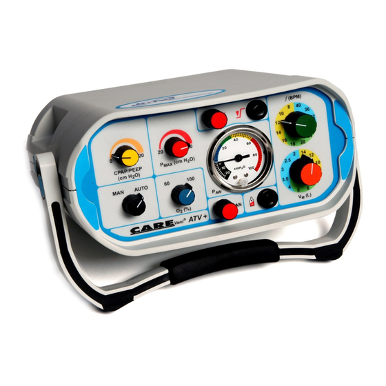
- Page 1 USER MANUAL (FOR STANDARD AND G2K® MODELS) CAREvent® ATV+ 01CV6000 CAREvent® ATV+ 01CV7000 CAREvent® ATV/ATV+ & MRI 01CV6000 01CV7000 01CV6000 01CV7000 CAREvent® ATV/ATV+ & MRI User Manual - REV 24 Mar, 2020...
-
Page 3: Table Of Contents
TABLE OF CONTENTS 1. Introduction 1.1. Warranty 1.2. Warnings 1.3. Terms and Defi nitions 1.4. CAREvent® MRI 1.5. General Information 1.6. General Description 1.7. Principles of Operation 1.8. Modes of Operation 1.9. Alarms and Gauges 1.10. Accessories 1.11. Control Adjustment 1.12. -
Page 4: Introduction
1. Introduction 1.1. Warranty WARRANTY The CAREvent® ATV+ and MRI are manufactured from the fi nest quality materials. Each individual part is subject to strict quality control tests to ensure exceptionally high standards. The manufacturer warrants to the purchaser of the Automatic Transport Ventilator that its component parts are free from defects in material and workmanship for a period of two years from the date of purchase. - Page 5 Do not disassemble any part of the ventilator except where described in this manual as any unauthorized disassembly will invalidate the warranty. 8. After use, always ensure that all components are cleaned in accordance with the instructions provided in this manual. (See section 4) 9.
-
Page 6: Terms And Defi Nitions
1.3. Terms and Defi nitions Airway Resistance: Pressure drop across the airway per unit fl ow. ATV: Automatic Transport Ventilator CMV: Controlled Mandatory Ventilation. A positive pressure applied to the lungs during all CPAP: ventilation phases (Continuous Positive Airway Pressure). A valve that delivers gas to the patient at a fl... -
Page 7: Carevent® Mri
A device which, when attached to the expiratory port of the patient valve, holds a positive pressure PEEP Valve: in the patients airway at the end of the expiratory phase. (Positive End Expiratory Pressure) Pressure Relief Valve which limits the maximum lung infl ation pressure Valve: by venting excess gas to atmosphere. -
Page 8: General Description
The G2K® models have been manufactured to comply with the latest Guidelines 2000 for CPR and ECC from the European Resuscitation Council and the American Heart Association. 1.6. General Description The CAREvent® ATV+ and MRI consist of a ruggedly constructed, portable control module, input hose and optional single use (or reusable where available) patient circuit. -
Page 9: Principles Of Operation
1.7. Principles of Operation The CAREvent® ATV+ and MRI are time-cycled, Intermittent Positive Pressure devices providing a range of frequencies of ventilation and Minute Volume settings to provide a comprehensive range of delivered tidal volumes and ventilation rates. The design of the micro-pneumatic circuitry in the Automatic Transport Ventilator maintains a consistent I:E ratio of 1:2 across the Minute Volume/frequency combinations to optimise the exchange of gases in the alveoli. - Page 10 In the Manual mode, depressing the Manual override button will allow the operator to manually ventilate the patient at a fl owrate equivalent to the Minute Volume selected. Demand Breathing During automatic ventilation, the Demand Breathing mode will allow the patient to commence spontaneous breathing through the ventilator while causing the automatic cycling to cease.
-
Page 11: Alarms And Gauges
ambient air into the system and automatically reduces the oxygen fl ow to maintain a consistent tidal volume. By using this mode the operating time on the cylinder supply is signifi cantly increased. Note: Due to the design of the micro-pneumatic circuit, increasing pulmonary resistance has little e ect on the delivered tidal volume or respiratory rate. - Page 12 Airway Over Pressure Alarm – Pressure Relief Continuous tone of a low pitch during the inspiratory phase of the ventilation that indicates that the maximum airway pressure selected has been reached. Inspiration Expiration p = Audible Pulsed Tone t = Time Fig.
-
Page 13: Accessories
Airway Pressure Gauge Located on the front panel of the ventilator, this gauge provides the operator with a visual indication of the airway pressure being reached during the ventilation cycle. 1.10. Accessories Supply Hose The supply hose is a standard armoured oxygen hose with a 9/16 DISS threaded connection for the ventilator. -
Page 14: Control Adjustment
1.11. Control Adjustment The ventilator is equipped with a number of selectors depending on the model. Each selector is actuated by the following method (Fig 4). Note: All selector positions are as viewed from the front of the ventilator. Ventilation Frequency (BPM): Located on the top right hand side of the control panel. -
Page 15: Technical Data
1.12. Technical Data (All specifi cations are subject to a tolerance of +/- 10% except the I:E Ratio which is subject to a tolerance of +/- 20% and Maximum Airway Pressure +0/-15%) Minute Volume Range: 2 - 14 L/min (+/- 10%) Frequency Range: 8 - 40 BPM (+/- 10%) I:e Ratio:... - Page 16 Audible pulsed alarm to indicate Low Input Pressure Alarm: input pressure is dropping below the minimum requirement. Cannot be switched o . Audible alarm to indicate that the Airway Pressure Alarm: selected peak airway pressure has been reached. Audible high frequency pulsed alarm indicating that the patient circuit is BSI Alarm: disconnected or insu cient...
-
Page 17: Preparation For Use
MRI Test Condition Parameters: The CAREvent® MRI has been tested in a 1.5 Tesla MRI environment (unshielded magnet - spatial gradient of < 23Mt/m/sec and a slew rate of 120 T/m/sec at an RF transmitter power of 2000 watts) and a 3.0 Tesla MRI environment (unshielded magnet - spatial gradient of <... -
Page 18: Connection Of Hoses
2.2. Connection of Hoses The supply hose provided is attached to the input connection on the side of the ventilator “fi nger tight” (fi g 5). WARNING Using a wrench or excessive force in tightening the supply hose may damage the seal or the thread of the connection. The patient circuit is attached to the gas outlet on the right hand side of the control module by simply pushing the 22 mm taper over the outlet. - Page 19 Testing of the Individual Features of the Ventilator. The following features can be individually tested during the pre- use Functional Check: Airway Over Pressure Alarm, Pressure Gauge Function and Pressure Relief Adjustment Function 2. Low Input Pressure Alarm 3. Frequency Adjustment 4.
- Page 20 As the ventilator cycles, gradually reduce the outlet pressure of the regulator until you hear the Low Input Pressure Alarm activate. This will be a slow, mid pitched, pulsed tone. Continue to decrease the regulator outlet pressure and the tone will gradually slow in frequency until it becomes a continuous tone.
- Page 21 5. Airmix Note: To fully test this function a calibrated 0 - 100% oxygen monitor is required (not supplied). With the ventilator connected to the 60 PSI medical oxygen source, set the frequency control to 8 BPM and the Minute Volume Selector set at 14 L, attach the oxygen monitor to the outlet of the patient connector.
-
Page 22: Operating Instructions
8. BSI Alarm With the Patient Circuit attached to the ventilator attach a test lung to the 15/22 mm adapter. Set the frequency control to 10 BPM and the Minute Volume Selector to the 6 L position. Turn the ventilator to AUTO and allow it to cycle for 5 breaths. Remove the test lung and time the delay until the BSI alarm sounds. -
Page 23: Operation In Extreme Conditions
This chart gives an easy reference to the delivered tidal volumes provided by the di erent combinations of frequency of respiration and minute volume. 3.3. Operation in Extreme Conditions Operation of the ventilator in environmental conditions outside of those detailed in this manual may result in a reduction in the ventilator’s performance. -
Page 24: Changing The Air Intake Filter
4.1.1. Changing the Air Intake Filter To change the air intake fi lter, undo the locking screw on the fi lter cover, which is located on the rear panel of the unit. Remove the old fi lter and discard following local protocols. Replace the fi lter with a new one ensuring that the fi... -
Page 25: Maintenance Schedule
5. Maintenance Schedule 5.1. Annual Preventative Maintenance Inspection It is recommended that the ventilator is returned to a service centre (authorized by the manufacturer to undertake service and repair of this device) for an Annual Preventative Maintenance inspection (more frequently in high use areas). The inspection will incorporate a full diagnostic test of all parameters. -
Page 26: Trouble Shooting Chart
6. Trouble Shooting Chart Note: If any of the remedies do not resolve the problem you are experiencing please contact your nearest Approved Service Centre. Symptom Probable Cause Remedy Gas supply Replace cylinder exhausted Gas supply not Open cylinder valve fully turned on ATV+ does not Supply hose... -
Page 27: Carevent® Accessories
Symptom Probable Cause Remedy Supply pressure too low Faulty gas (Low Input Pressure supply regulator Alarm will sound) Gas supply cylinder Replace cylinder low or empty. Demand fl owrate low Regulator output insu cient Replace regulator or not functioning Cylinder valve not fully open Open valve fully Brand of circuit used may Use only O-Two... - Page 28 Your Representative is: O-TWO MEDICAL TECHNOLOGIES INC. For your nearest Authorized O-Two Distributor In North America call Toll Free 1-800-387-3405 MedNet EC-REP GmbH SERIAL N Borkstrasse, 10 48163 Münster, Germany www.otwo.com 45A Armthorpe Road, Brampton, ON, Canada, L6T 5M4 Telephone: +1 905 792-OTWO (6896) N.A. Toll Free: +1 800 387 3405 Facsimile: +1 905 799 1339 Email: resuscitation@otwo.com...
Need help?
Do you have a question about the CAREvent ATV and is the answer not in the manual?
Questions and answers