
Related Manuals for O_TWO e600

Summary of Contents for O_TWO e600
- Page 1 USER MANUAL o_two e600 AUTOMATIC TRANSPORT VENTILATOR 01EVE600 e600 User Manual (15PL1010 - Rev.8 Feb 2021)
-
Page 3: Table Of Contents
TABLE OF CONTENTS 1. Safety 2. Intended Use 3. Overview 3.1. Control and Display Layout 3.2. Function Keys 3.2.1. ON/OFF 3.2.2. Control Selection Knob 3.2.3. Lock 3.2.4. Alarm Silence 3.2.5. Waveform 3.2.6. Screen Brightness 3.2.7. Cancel 3.2.8. Pause/Resume 3.2.9. Manual / Inspiratory Hold 3.3. - Page 4 5.2.3. CPAP (Continuous Positive Airway Pressure) 5.2.4. CPR mode 5.3. Turning Ventilator OFF 6. Post use 6.1. Disconnect device after use 6.2. Storage 7. Alarms and Indicators 7.1. Ventilation Alarms 7.2. Battery status indicator 7.3. LEDs 8. Cleaning, Preventive Maintenance & Servicing 8.1.
-
Page 5: Safety
1. Safety WARNING • U.S. Federal Law restricts this device to sale by or on the order of a physician. • The ventilator shall only be used for the purposes specified under “Intended Use”. • The ventilator should only be used by qualified personnel trained in its use. - Page 6 • Do not use this ventilator within a Magnetic Resonance Imaging (MRI, NMR, NMI) suite. • Do not use this ventilator in hyperbaric (high pressure) chambers. • Do not use the external electrical power supply outdoors as moisture may affect its function. •...
- Page 7 • Operation of this ventilator below sea level or above 4,000 m (13,000 feet) may result in reduction or failure in the ventilator’s performance, low pressure alarm or possible loss of automatic cycling. • The ventilator is intended for use in the prehospital, intrahospital, interhospital and ground transport environments only.
-
Page 8: Intended Use
2. Intended Use The e600 is a time-cycled and volume-constant emergency and transport ventilator designed for use in the pre-hospital, intra- hospital, inter-hospital and transport settings. It is intended for use... -
Page 9: Overview
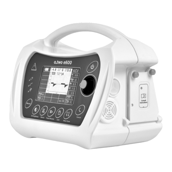
3. Overview 3.1. Control and Display Layout Figure 01 Warning indicator Pause/Resume key Battery operation indicator Lock key External power indicator Waveform selection key Battery charging indicator Cancel key Manual/Inspiratory Hold key Confirmation indicator light Screen brightness key Control Selection Knob Alarm Silence key ON/OFF key e700 User Manual... -
Page 10: Function Keys
3.2. Function Keys While all ventilation parameter settings are controlled by the Control Selection Knob (M) in Figure 1, there are a number of key membrane buttons which control additional ventilator functions: 3.2.1. ON/OFF To turn on the ventilator, Press the ON/OFF button (N) in Figure 01 for one second, during that second the associated green LED will start flashing at a high frequency. -
Page 11: Lock
3.2.3. Lock Lock function will disable all buttons and the Control Selection Knob except for the ON/OFF, Alarm Silence and Day/Night buttons, which are enabled at all times. To lock the key membrane or cancel the lock function: Press the Lock key (I) (Figure 01). The Lock symbol will be displayed on the screen. -
Page 12: Screen Brightness
3.2.6. Screen brightness Pressing the Screen Brightness key (F) (Figure 01) will switch between 4 different brightness levels as follows: Light background with dark color text and waveform at 100% light intensity. 2. Light background with dark colored text and waveform at 35% light intensity. -
Page 13: Manual/Inspiratory Hold
3. Once activated, a flashing yellow pause symbol will be displayed on the screen and the ventilator will pause ventilation. Note: A. During Pause, there will be an audible alarm associated with a flashing yellow Warning indicator (A) (Figure 01) every 15 seconds. -
Page 14: External Connectors
3.3. External Connectors DC Input connector Air Intake filter Sensor connector #1 Sensor connector #2 22mm gas output connector Gas supply input Battery door Relieve Flapper Air/O Exhaust Port Figure 02 e700 User Manual... -
Page 15: Patient Circuit
3.4. Patient circuit λ Figure 03 Breathing Control Hose Breathing Valve Sensing hoses Flow sensor adapter One Way Intake Valve Elbow λ Exhalation port Note: To avoid entanglement of the patient circuit tubing and pressure sensing hoses during movement of the patient, the pressure sensing hoses and the 22mm corrugated hose are contained within in a close fitting, non-woven fabric sheath. -
Page 16: Display
3.5. Display 3.5.1. Screen Layout The screen is divided into 7 sections as shown below and each section is dedicated to display the following parameters: Section 1: Battery status during charge and discharge. Live ventilation parameters (Vte, Mve, Paw , Paw peak Section 2: Rate) - Page 17 The followings are screen layouts for each ventilation mode: A/C screen layout SIMV screen layout e700 User Manual...
- Page 18 CPAP screen layout CPR screen layout e700 User Manual...
-
Page 19: Live Monitoring Parameters
3.5.2. Live Monitoring Parameters The following Live Monitoring Parameters are displayed at the section 2 of the screen: (cmH O): Paw AV is the average patient airway pressure measured during the last 60 seconds. This measurement is monitored by the ventilator at all times and modes. The number on the display will be updated every 15 seconds. -
Page 20: Symbols & Notations
3.6. Symbols and Notations Consult instructions for use. Warning! Risk of injury and possible negative patient outcome. Warns of material damage and negative patient outcome. Offers useful tips to assist in the proper use of the equipment. Confirmation Symbol Invalid Setting Symbol Conflict Setting Symbol Keep away from open flames. -
Page 21: Preparation For Use
4. Preparation for Use 4.1. Setup 4.1.1. Connecting the electrical power supply The e600 is designed to operate using one of the following power options: • Internal rechargeable battery pack • AC/DC external power supply. CAUTION • A fully charged battery must always be installed for safety... -
Page 22: Connecting The Gas Supply
3. Turn cylinder valve slowly and fully. WARNING Extra care must be taken when handling oxygen: • The e600 must only be used with medical oxygen. • Only use approved medical oxygen compressed gas cylinders. • Always begin use with a full oxygen cylinder. -
Page 23: Connecting Patient Circuit
If the key is pressed and released for less than one second, the ventilator will remain OFF. Note: A/C V with volume control (VCV) is the default start-up ventilation mode for the e600. 4.2. Pre-use Checks The following checks must be performed and confirmed by the healthcare provider in the following cases: •... - Page 24 Visually inspect the ventilator for mechanical damage 2. Ensure that battery is fully charged. 3. Ensure the e600 is connected to a gas supply (Cylinder or piping system) capable of delivering flow of 120 L/min and maintaining a minimum pressure of 45 PSI (3 Bar) and a maximum 87 PSI (6 Bar) output pressure.
- Page 25 Input Leak Test Once all connections are verified, open the cylinder valve slowly, at least two full turns, counter clockwise. From the pressure regulator gauge reading, ensure the cylinder pressure is above 650 PSI (45 bar) otherwise replace with new oxygen cylinder. Once pressurized, turn off the oxygen cylinder and observe the output pressure on the gauge of the regulator.
- Page 26 Function check After confirming no leaks are present in the ventilator, input hose and patient circuit, with the mains electrical supply connected, proceed as follows: Turn on the ventilator and select child default setting by depressing the control knob (M) (Figure 01). 2.
-
Page 27: Operate Instructions
5. Operating Instructions 5.1. Start Up and Setting the Ventilation Parameters A. Turn on the ventilator: Ensure that the gas supply is turned on before start up to ensure that the calibration process is performed correctly. To turn on the ventilator, press the ON/ OFF key (N) (Figure 01) for one second. - Page 28 01:23:48 PM o-two e600 v1.9.15 11/07/20 Figure 06 - Start-up Figures Navigate among the three start-up figures by rotating the Control Selection Knob (M) (Figure 01) and a square frame will move around the selected figure. Once the desired patient size is selected, the user must confirm the selection by pressing the Control Selection Knob (M) (Figure 01) to start ventilation.
- Page 29 Connect the patient valve to the patient; the ventilator will commence volume controlled A/C V ventilation with the default parameters selected (as listed in Table 1) depending on the selected patient size (Figure 07). The user can pause the ventilation by pressing the Pause/Resume key (H) (Figure 01) and adjust the parameters to the patient’s requirements before commencing ventilation if necessary.
- Page 30 C. Set up the desired ventilation settings: Health care providers may choose or change the ventilation mode or parameter setting any time during ventilation by the following method: Rotate the Control Selection Knob (M) (Figure 01) and move the yellow cursor (Figure 08) to section 3 of the screen (Figure 04) for ventilation mode setup, or to the parameter to be set up located at section 6 of the screen (Figure 04).
-
Page 31: Ventilation Modes
10 seconds, changes will be cancelled and the previous parameter values will remain. 5.2. Ventilation Modes The e600 ventilator is equipped with a number of ventilation modes to enable the healthcare provider to tailor the ventilator settings to the patient’s specific respiratory requirements. Ventilation could be delivered invasively (ET tube) or non-invasively (mask). -
Page 32: A/C V (Assist Control Ventilation)
Leak Compensation In all ventilation modes the ventilator will automatically compen- sate up to 30% of the required tidal volume Vt in case a leak is de- tected. Beyond this limit, low Paw visual and audible alarms will be activated to warn rescuer to either re-apply the mask or increase the set tidal volume. - Page 33 TABLE 2 - Default Ventilation Setting- A/C V DEFAULT PARAMETER RANGE INFANT CHILD ADULT Tidal Volume (50 - 2000 ml) Rate (5 - 60 BPM) Calculated based on Vt & f I:E ratio (1:4 – 3:1) (0.2 – 9 sec.) 0.66 1.33 PEEP...
-
Page 34: Simv (Synchronized Intermittent Mandatory Ventilation)
5.2.2. SIMV (Synchronized Intermittent Mandatory Ventilation) In this mode the ventilator will deliver volume ventilation at the set Tidal Volume (Vt) and Rate (bpm) The default trigger for this mode is 3 L/min but can be adjusted up to 15 L/min. if trigger condition is met, the ventilator will deliver synchronized volume controlled mandatory ventilation. - Page 35 TABLE 3 - Default Ventilation Setting- SIMV DEFAULT PARAMETER RANGE INFANT CHILD ADULT Tidal Volume (50 - 2000 ml) Rate (5 - 60 BPM) Calculated based on Vt & f I:E ratio (1:4 – 3:1) (0.2 - 9 sec) 0.66 1.33 PEEP (OFF, 4-20 cm H...
-
Page 36: Cpap (Continuous Positive Airway Pressure)
5.2.3. CPAP (Continuous Positive Airway Pressure) In CPAP mode, the ventilator will deliver a continuous flow rate to generate airway pressure and use the control valve to maintain CPAP levels (Figure 12). Note: The default trigger in CPAP mode is pressure trigger (P) which is set at 2 cm H O below CPAP settings. - Page 37 TABLE 4 - Default Ventilation Setting- CPAP DEFAULT PARAMETER RANGE INFANT CHILD ADULT CPAP (4-20 cm H (P or 1 -15 L/min) Trig. P = 2 cm H O below base line (100% or 60%) 100% 100% 100% T APNEA (10-60 seconds) Vt(A) (50 - 2000 ml)
-
Page 38: Cpr Mode
5.2.4. CPR mode The CPR mode consists of timed chest compression audible prompts coupled with automatically delivered breaths for both intubated and mask ventilated patients. There is also a visual animated display to guide the health care provider while performing CPR. The CPR mode for masked ventilated patients is the default setting for this mode but changes can be made between the 2 sub-modes at any time. - Page 39 TABLE 5 - Default Ventilation Setting- CPR DEFAULT PARAMETER RANGE INFANT CHILD ADULT Tidal Volume (50 - 1400 ml) P max. (10 -80 cm H (0-20 cm H P min. during I time only) CPR FOR MASKED PATIENTS On screen chest compressing animation On screen ventilation animation Figure 13.a - CPR waveform for masked patient e700 User Manual...
-
Page 40: Turning Ventilator Off
On screen intubated CPR animation CPR FOR MASKED PATIENTS 100 times chest compressions per minute Flow Flow Ventilation frequency: 10 bpm Figure 13.b - CPR waveform for intubated patient 5.3. Turning the Ventilator Off Press and hold the ON/OFF key for 4 seconds, the Ventilator will turn OFF. -
Page 41: Post Use
6. Post Use 6.1. Disconnect device after use A. Turn off gas supply to the ventilator. B. Disconnect gas supply hose. C. Disconnect patient circuit from the output connector. D. Unplug the power cable from mains if no charging is required. E. - Page 42 In this case the visible and audible alarms will be based on highest priority alarm. All ventilation alarms of e600 are listed in the following Table-6. TABLE 6 - Ventilation Alarms and Symbols Visual Alarm...
- Page 43 Visual Alarm Audible Symbol Name Priority Alarm Alarm Symbol Warning LED Two bursts with Empty Battery High Flashing symbol five pulses Low Battery Flashing symbol Yellow every 15 Pause Flashing symbol seconds Play Flashing symbol Lock Solid symbol Alarm Silence Solid symbol Solid symbol Patient effort...
-
Page 44: Battery Status Indicator
7.2. Battery Status Indicator The battery status will be displayed in section 1 of the display (Figure 04). There are two different status indicators showing battery discharging (Table-7.1) and charging (Table-7.2) status respectively. TABLE 7.1 - Battery discharging status Full Capacity Approx. -
Page 45: Leds
WARNING At approximately 2% of full battery capacity, the ventilator will not start when it is turned off or will shut down when it is turned on. Note: The battery capacity level is detected from measured voltages and the capacities shown above are based on results from new batteries tested at room and low temperature. -
Page 46: Cleaning, Preventive Maintenance & Servicing
Make sure no liquids enter the ventilator connections or the ventilator. WARNING Do not immerse the e600 Ventilator or patient circuit or supply hoses in disinfectant or other liquids, serious electric shock hazard and damage to the ventilator may occur. If the Ventilator is accidently submerged in any liquid it must be returned to the manufacturer for factory service. -
Page 47: Ambient Air Entrainment Filter
5 hours on a single charge. 8.3. Ambient Air Entrainment Filter The e600 entrains ambient air through the internal Venturi system for ventilation when the O concentration is set at 60%. This provides not only decreased oxygen concentration but also increases the ventilator operating time on an oxygen cylinder. -
Page 48: Preventive Maintenance And Servicing
8.4. Preventive Maintenance and Servicing It is recommended that routine preventive maintenance (PM) and servicing shall be carried out as per the following: TYPE DESCRIPTION PROCEDURE CRITERIA SCHEDULE Charging User Manual Battery fully Every 6 User battery Chapter 8.2 charged months User Manual No leak... -
Page 49: Technical Data
9. Technical Data 9.1. Specifications DEVICE CLASS PER MDD II b Protection against Class II, Type BF CLASSIFICATION electric shock PER IEC60601-1 Protection against water IP X4 POWER SOURCE (PNEUMATIC) Compressed Oxygen, 45 to 87 PSI (3-6 Bar) AC/DC power supply, POWER SOURCE (ELECTRIC) Rechargeable Lithium Battery VENTILATION MODES... - Page 50 * Volume measurements corrected to BTPS (Body Temperature 37 C, barometric Pressure 101.3Kpa under Saturated 100% humidity) conditions. **Transient Operation: The e600 is capable to keep its specifications when operated in normal use for a period not less than 20 minutes under - 20 C and +50 C.
-
Page 51: Circuit Description
Ambient Filter Ventilator When a gas source (medical oxygen) is supplied to the e600 ventilator via the gas input connection, the gas will flow into the Flow control valve which is used to control both the flow and rate of ventilation. -
Page 52: Battery Operating Time
O-Two e600 has been tested and complies with IEC 60601-1-2:2007 requirements. Electromagnetic Emissions O-Two e600 is intended for use in the electromagnetic environment specified below. The user of O-Two e600 should assure that it is not used in environments outside those specified: e700 User Manual... - Page 53 30 V/m IEC61000-4-3 80 MHz to 2.5 GHz O-Two e600 is intended for use in the electromagnetic environment in which radiated RF disturbances are controlled. The user can help prevent electromagnetic interference by maintaining a minimum distance between portable and mobile RF...
-
Page 54: Oxygen Consumption
9.6. Oxygen Consumption For a “D” size cylinder (capacity of 425 liters), pressurized to 2015 PSI and with the e600 set to the Adult default setting (Vt= 500ml, Rate= 10BPM, 100% Oxygen) the pneumatic operating time is 85 minutes without PEEP (0.2 min/L) and is 39 minutes with maximum PEEP (0.089 min/L). -
Page 55: Trouble Shooting
Battery No proper charging/Faulty Charge Battery as per instructions/ discharges battery Replace battery quickly Change Battery/connect power e600 cannot be Battery empty/no power supply supply/ send to O-Two for repair or switched on connected/defective service e700 User Manual... -
Page 56: Abbreviations And Acronyms
11. Abbreviations and Acronyms TERM DESCRIPTION A/C V Assist Control Ventilation Breathing Circuit Integrity (Patient circuit disconnect) CPAP Continuous Positive Airway Pressure Cardio Pulmonary Resuscitation Rate Ventilation rate (number of breaths per minute) Ratio of inspiration time to expiration time Light Emitting Diode Exhaled Minute Volume Minute volume... -
Page 57: Accessories
13. Warranty O-Two Warrants the e600 ventilator, when used in accordance with the instructions contained within this Manual, for a period of two years from the date of purchase except for the following cases: Using unspecified parts/accessories 2. - Page 58 WARNING It is recommended that the routine preventive maintenance shall be carried out at least every 6 months from date of purchase. Repair and general overhaul of the ventilator must be carried out by trained service personnel. Evaluation of performance against manufacturer’s specifications may be undertaken by suitably qualified personnel to determine if the ventilator is functioning within specification.
- Page 60 Your Representative is: O-TWO MEDICAL TECHNOLOGIES INC. For your nearest Authorized O-Two Distributor In North America call Toll Free 1-800-387-3405 MedNet EC-REP GmbH SERIAL N Borkstrasse, 10 48163 Münster, Germany www.otwo.com 45A Armthorpe Road, Brampton, ON, Canada, L6T 5M4 Telephone: +1 905 792-OTWO (6896) N.A. Toll Free: +1 800 387 3405 Facsimile: +1 905 799 1339 Email: resuscitation@otwo.com...
Need help?
Do you have a question about the e600 and is the answer not in the manual?
Questions and answers