Table of Contents
Advertisement
Available languages
Available languages
Quick Links
DEUTSCH
ENGLISH
18
FRANÇAIS
33
ITALIANO
48
Ab Serie-Nr. 100
From serie no 100
A partir du no de série 100
A partire dal no. di serie 100
Vor dem Gebrauch des
Gerätes die Betriebs-
anleitung aufmerksam
lesen.
Before using the tool,
read the operating
instructions carefully.
Avant l'utilisation de
l'appareil, consultez
soigneusement le
mode d'emploi.
Prima d'utilizzare
l'apparecchio, leggere
attentamante le istru-
zioni per l'uso.
08.03/WE
BETRIEBSANLEITUNG UND SICHERHEITSVORSCHRIFTEN
BETRIEBSANLEITUNG UND SICHERHEITSVORSCHRIFTEN
BETRIEBSANLEITUNG UND SICHERHEITSVORSCHRIFTEN
BETRIEBSANLEITUNG UND SICHERHEITSVORSCHRIFTEN
BETRIEBSANLEITUNG UND SICHERHEITSVORSCHRIFTEN
3
OPERA
OPERA
OPERATING
OPERA
OPERA
TING AND SAFETY INSTR
TING
TING
TING
MODE D'EMPLOI ET DE SÉCURITÉ
MODE D'EMPLOI ET DE SÉCURITÉ
MODE D'EMPLOI ET DE SÉCURITÉ
MODE D'EMPLOI ET DE SÉCURITÉ
MODE D'EMPLOI ET DE SÉCURITÉ
ISTRUZIONI PER L'USO E DI SICUREZZA
ISTRUZIONI PER L'USO E DI SICUREZZA
ISTRUZIONI PER L'USO E DI SICUREZZA
ISTRUZIONI PER L'USO E DI SICUREZZA
ISTRUZIONI PER L'USO E DI SICUREZZA
OR-H 20 A
Handgerät zum Umreifen mit Stahlband
Hand tool for steel strapping
Appareil pour le cerclage par feuillard d'acier
Apparecchio per reggiare con reggetta d'acciaio
AND SAFETY INSTR
AND SAFETY INSTR
AND SAFETY INSTRUCTIONS
AND SAFETY INSTR
UCTIONS
UCTIONS
UCTIONS
UCTIONS
Advertisement
Chapters
Table of Contents

Related Manuals for Orgapack 100 Series


Summary of Contents for Orgapack 100 Series
- Page 1 BETRIEBSANLEITUNG UND SICHERHEITSVORSCHRIFTEN BETRIEBSANLEITUNG UND SICHERHEITSVORSCHRIFTEN BETRIEBSANLEITUNG UND SICHERHEITSVORSCHRIFTEN BETRIEBSANLEITUNG UND SICHERHEITSVORSCHRIFTEN BETRIEBSANLEITUNG UND SICHERHEITSVORSCHRIFTEN DEUTSCH OPERA OPERA OPERATING OPERA OPERA TING TING TING TING AND SAFETY INSTR AND SAFETY INSTR AND SAFETY INSTR AND SAFETY INSTR AND SAFETY INSTRUCTIONS UCTIONS UCTIONS UCTIONS...
- Page 2 ORGAPACK OR-H 20 A ORGAPACK GmbH KONFORMITÄTSERKLÄRUNG Standard-Umreifungstechnik (SST) Silbernstrasse 14 Wir erklären in alleiniger Verantwortung, dass das CH-8953 Dietikon Gerät OR-H 20 A, auf das sich diese Erklärung Telefon +41 1 745 50 50 bezieht, mit den geltenden Bestimmungen des +41 1 745 52 64 STEG (Bundesgesetz über die Sicherheit von...
-
Page 3: Table Of Contents
ORGAPACK OR-H 20 A INHALTSVERZEICHNIS TECHNISCHE DATEN Seite Gewicht 9,7 kg 1 Technische Daten 2 Allgemeines Abmessung Länge 310 mm 2.1 Hinweis zum Umweltschutz Breite 105 mm 3 Sicherheitsvorschriften Höhe 240 mm 4 Beschreibung 4.1 Aufbau Spannkraft Bis ca. 4000 N 4.2 Funktionsprinzip... -
Page 4: Allgemeines
ORGAPACK OR-H 20 A ALLGEMEINES Diese Betriebsanleitung soll das Kennenlernen des Gerätes und den bestimmungsgemässen Einsatz VORSICHT! erleichtern. Die Betriebsanleitung enthält wichtige Hinweise, wie das Gerät sicher, sachgerecht und Wird verwendet bei wirtschaftlich einzusetzen ist. Das Einhalten der Gefahren für Leben Hinweise hilft Gefahren vermeiden, Reparaturen und und Gesundheit. -
Page 5: Sicherheitsvorschriften
ORGAPACK OR-H 20 A SICHERHEITSVORSCHRIFTEN Informieren Sie sich! Keine Gas- oder Vor dem Gebrauch des Druckluftflaschen ver- jklsfjklsdj Gerätes die Betriebsanlei- wenden! lksdfjkl jkljsdllkjjkljsd fkljjklkjkljsdafj asdfjklkjjkljklj tung sorgfältig lesen. ksldafkjkljkl Das Gerät darf nicht an jkljklkljsdafjlkj jkljjkljklkljljlk eine Gas- oder Druckluft- Schützen Sie sich! -
Page 6: Beschreibung
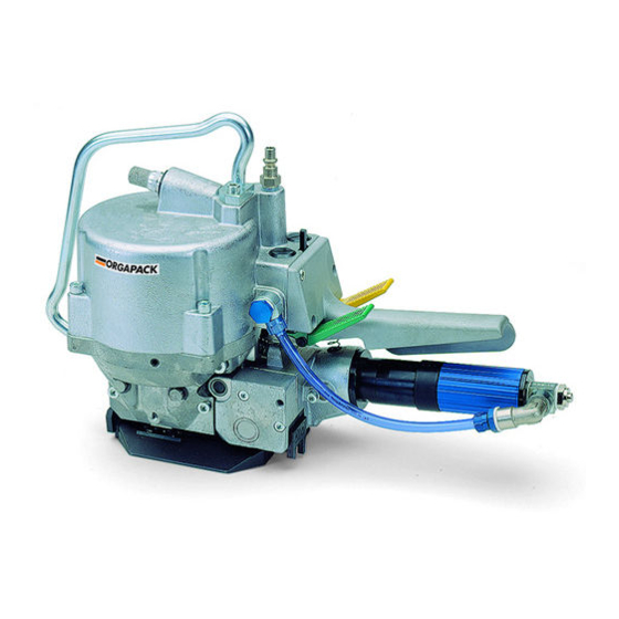
ORGAPACK OR-H 20 A BESCHREIBUNG 4.1 AUFBAU 1 Luftanschluss 2 Klinke (Spannvorgang unterbrechen) 3 Gelbe Taste (Verschliessen) 4 Grüne Taste (Spannen) 5 Handgriff 6 Druckluftmotor 7 Druckreduzierventil 8 Spannrad 9 Matrize 10 Grundplatte 11 Verschliesszangen 12 Aufhängebügel Fig. 1 4.2 FUNKTIONSPRINZIP –... -
Page 7: Inbetriebnahme
ORGAPACK OR-H 20 A INBETRIEBNAHME 5.1 AUFHÄNGEN DES GERÄTES Horizontal Das Gerät ist mit einem Aufhängebügel (3/1) ausge- stattet. Der Aufhängebügel ist so konstruiert, dass das Gerät horizontal oder vertikal an einem Federzug auf- gehängt werden kann. Als Option ist ein Universalbügel erhältlich, der zusätz- lich eine seitliche Aufhängung des Gerätes gestattet. -
Page 8: Bedienung
ORGAPACK OR-H 20 A BEDIENUNG 6.1 BEDIENUNG DES GERÄTES – Band von der Rolle abziehen und satt um das Umreifungsgut legen. Band ca. 30 cm vor dem Band- anfang mit der linken Hand fassen. – Gerät mit der rechten Hand am Griff fassen und den Motor bis zum Anschlag hochziehen. - Page 9 ORGAPACK OR-H 20 A Verschliessen – Mit dem Daumen der rechten Hand die gelbe Taste (7/1) betätigen, bis das Band abgeschnitten ist. Fig. 7 – Gerät mit der rechten Hand am Griff fassen und den Motor bis zum Anschlag hochziehen und das Gerät nach hinten rechts von der Umreifung weg- schwenken.
-
Page 10: Wartung Und Instandsetzung
ORGAPACK OR-H 20 A WARTUNG UND INSTANDSETZUNG 7.1 SPANNKRAFT/SPANNGESCHWINDIGKEIT EINSTELLEN – Luftdruck am Druckreduzierventil der Wartungeinheit auf 5–6 bar einstellen. – Mit Schraubenzieher Drosselschraube (10/1) des Druckluftmotors so einstellen, dass bei gewünsch- ter Bandspannung der Druckluftmotor zum Stillstand kommt. Dabei ist darauf zu achten, dass die Bänder einwandfrei gekerbt und das obere Band abgeschnit- ten wird. -
Page 11: Spannrad Ersetzen
ORGAPACK OR-H 20 A 7.4 SPANNRAD ERSETZEN Dreht das Spannrad durch, bevor die ge- wünschte Bandspannung erreicht ist, muss das Spannrad ersetzt werden (Voraussetzung: Spiel richtig eingestellt, siehe Kapitel 7.2). Ausbau – Gerät von Luftanschluss trennen. – Eine Senkschraube (13/1) entfernen. -
Page 12: Abschneidmesser, Matrize Und Stempel Ersetzen
ORGAPACK OR-H 20 A 7.6 ABSCHNEIDMESSER, MATRIZE UND STEMPEL ERSETZEN Ausbau – Gerät von Luftanschluss trennen. – Zwei Zylinderschrauben (15/9), Anschlagplatte (15/10) und Bandhalteklinke (15/8) entfernen. – Vier Zylinderschrauben (15/6) entfernen. – Grundplatte (15/5) vom Gehäuseteil entfernen. – Zwei Zylinderschrauben (15/3) lösen und Matrize (15/2) entfernen und ersetzen. -
Page 13: Teileliste
ORGAPACK OR-H 20 A TEILELISTE 1831.002.002/1 Bei Bestellungen Artikel-Nr. und Stückzahl angeben Explosionszeichnung: siehe Seite 15 Empfohlene Ersatzteile Pos. Artikel-Nr. Benennung Stück Pos. Artikel-Nr. Benennung Stück 4 5 1173.500.012 Halter 1 1173.940.002 Grundplatte 13 mm 4 6 1910.608.122 Gewindestift, M 8 x 12 inkl. - Page 14 ORGAPACK OR-H 20 A Pos. Artikel-Nr. Benennung Stück Pos. Artikel-Nr. Benennung Stück 149 1941.112.720 L-Verschraubung, G 1/4“ 9 3 1820.070.014 Manschette 9 4 1820.010.123 Druckfeder 150 1940.070.723 Drosselrückschlagventil, G 1/4“ 9 5 1820.030.308 Entlüfterschraube 151 1941.102.720 Ringstück, G 1/4“ 9 6 1940.401.720 Schalldämpfer, G 1/4“...
-
Page 16: Teileliste Druckluftmotor
ORGAPACK OR-H 20 A TEILELISTE DRUCKLUFTMOTOR 1894.332.000/2 Bei Bestellungen Artikel-Nr. und Stückzahl angeben Explosionszeichnung: siehe Seite 17 Pos. Artikel-Nr. Benennung Stück 1 1894.332.011 Endplatte 2 1894.332.010 Getriebegehäuse (Rückseite) 3 1894.332.013 Schalldämpfer 4 1894.332.033 Sieb 5 1894.332.002 Kugellager 6 1894.332.003 Lagerplatte hinten 7 1894.332.001... -
Page 18: Npt)
ORGAPACK OR-H 20 A TABLE OF CONTENTS TECHNICAL DATA Page Weight 9.7 kg (21.3 lbs) 1 Technical data 2 General information Dimensions Length 310 mm (12.2") 2.1 Information on environmental protection Width 105 mm (4.1") Height 240 mm (9.5") 3 Safety instructions... -
Page 19: General Information
ORGAPACK OR-H 20 A GENERAL INFORMATION These operating instructions are intended to simplify familiarisation with the strapping tool and the possibili- CAUTION! ties of application for the intended purpose. The operat- ing instructions contain important information concern- Used where there is ing the safe, proper and efficient use of the strapping danger to life and health. -
Page 20: Safety Instructions
ORGAPACK OR-H 20 A SAFETY INSTRUCTIONS Do not use a bottled Inform yourself! air or gas source! Read the operating Do not operate this tool instructions carefully. jklsfjklsdj lksdfjkl jkljsdllkjjkljsd fkljjklkjkljsdafj by using a bottled air or asdfjklkjjkljklj ksldafkjkljkl jkljklkljsdafjlkj jkljjkljklkljljlk gas source. -
Page 21: Description
ORGAPACK OR-H 20 A DESCRIPTION 4.1 DESIGN 1 Compressed air connection 2 Pawl (Interrupting tensioning process) 3 Yellow button (Sealing) 4 Green button (Tensioning) 5 Handle 6 Compressed air motor 7 Pressure reduzing valve 8 Tension wheel 9 Tension plug... -
Page 22: Initial Operation
ORGAPACK OR-H 20 A INITIAL OPERATION 5.1 SUSPENDING THE TOOL Horizontally The tool can be suspended on a spring balancer with the suspension bracket (3/1) supplied. The suspension bracket is designed to operate the tool horizontally or vertically. Optionally a suspension bracket is available to operate the tool also sideways. -
Page 23: Operating Instructions
ORGAPACK OR-H 20 A OPERATING INSTUCTIONS 6.1 OPERATING THE TOOL – Draw strap from reel and place tightly around the package. Grip strap with the left hand approx. 30 cm (12") from the beginning of the strap. – Hold the handle of the tool in the right hand and raise the motor up to the stop. - Page 24 ORGAPACK OR-H 20 A Sealing – Press the yellow button (7/1) with the right thumb until the strap is cut off. Fig. 7 – Raise the motor to the stop and swing the tool away to the right. Fig. 8 Check of seal min.
-
Page 25: Preventive And Corrective Maintenance
ORGAPACK OR-H 20 A PREVENTIVE AND CORRECTIVE MAINTENANCE 7.1 ADJUSTING TENSIONING FORCE/ TENSIONING SPEED – Set air pressure at pressure reducing valve of maintenance unit to 4–6 bar. – With a screwdriver adjust pressure reducing valve (10/1) of air motor, so that the motor stops when the required tension is reached. -
Page 26: Replacing Tension Wheel
ORGAPACK OR-H 20 A 7.4 REPLACING TENSION WHEEL If the tension wheel spins before the required strap tension is reached, the tension wheel must be replaced (precondition: clearence set correctly, see chapter 7.2). Remove – Disconnect tool from air supply. -
Page 27: Replacing Knife, Die And Die Plate
ORGAPACK OR-H 20 A 7.6 REPLACING KNIFE, DIE AND DIE PLATE Remove – Disconnect tool from air supply. – Remove two cylinder screws (15/9), stop plate (13/10) and strap holding pawl (15/8). – Remove four cylinder screws (15/6). – Withdraw base plate (15/5) from housing. -
Page 28: Parts List
ORGAPACK OR-H 20 A PARTS LIST 1831.002.002/1 When ordering please indicate part number and quantity Explosion drawing see page 30 Recommended spare parts Pos. Part no Part name Quantity Pos. Part no Part name Quantity 4 5 1173.500.012 Holder 1 1173.940.002... - Page 29 ORGAPACK OR-H 20 A Pos. Part no Part name Quantity Pos. Part no Part name Quantity 9 4 1820.010.123 Compression spring 149 1941.112.720 L-Fitting, G 1/4“ 9 5 1820.030.308 Air release screw 9 6 1940.401.720 Silencer, G 1/4“ 150 1940.070.723 One way restrictor, G 1/4“...
-
Page 31: Parts List Compressed Air Motor
ORGAPACK OR-H 20 A PARTS LIST COMPRESSED AIR MOTOR 1894.332.000/2 When ordering please indicate part number and quantity Explosion drawing see page 32 Pos. Part no Part name Quantity 1 1894.332.011 End plate 2 1894.332.010 Gear housing (Rear side) 3 1894.332.013 Silencer 4 1894.332.033... - Page 33 ORGAPACK OR-H 20 A TABLE DES MATIÈRES DONNÉES TECHNIQUES Page Poids 9,7 kg 1 Données techniques 2 Instructions générales Encombrement Longueur 310 mm 2.1 Remarque relative à la protection de Largeur 105 mm Hauteur 240 mm l'environnement 3 Instructions de sécurité...
-
Page 34: Instructions Générales
ORGAPACK OR-H 20 A INSTRUCTIONS GÉNÉRALES Ces instructions de service doivent faciliter la con- naissance de l'appareil et les possibilités d'utilisation PRUDENCE! selon les règles. Les instructions de service contien- nent d'importants renseignements, à savoir comment Utilisé si risque de mort l'appareil doit fonctionner en toute sécurité, selon les... -
Page 35: Instructions De Sécurité
ORGAPACK OR-H 20 A INSTRUCTIONS DE SÉCURITÉ Bouteilles gaz ou d‘air Renseignez-vous! comprimé interdites! Avant l'utilisation de Interdiction de branche- l'appareil, consultez jklsfjklsdj lksdfjkl jkljsdllkjjkljsd ment de l‘appareil à une fkljjklkjkljsdafj soigneusement le mode asdfjklkjjkljklj ksldafkjkljkl jkljklkljsdafjlkj jkljjkljklkljljlk bouteille de gaz ou d‘air d'emploi. -
Page 36: Description
ORGAPACK OR-H 20 A DESCRIPTION 4.1 MODULES PRINCIPAUX 1 Raccordement air comprimé 2 Cliquet d’arrèt (Interruption de la tension) 3 Touche jaune (sertissage) 4 Touche verte (serrage) 5 Levier 6 Moteur à air comprimé 7 Soupape réductrice 8 Molette de tension... -
Page 37: Mise En Service
ORGAPACK OR-H 20 A MISE EN SERVICE 5.1 SUSPENSION DE L‘APPAREIL L’appareil peut être suspendu à un câble avec ressort Horizontalement par le crochet (3/1) compris dans la livraison. Ce crochet est conçu pour que l’appareil puisse être suspendu horizontalement ou verticalement. -
Page 38: Mode D'emploi
ORGAPACK OR-H 20 A MODE D‘EMPLOI 6.1 MODE D‘EMPLOI POUR L‘APPAREIL – Dérouler le feuillard et le disposer autour de la marchandise à cercler. Saisir avec la main gauche le feuillard à environ 30 cm de son début. – Saisir avec la main droite l’appareil et relever le moteur jusqu’à... - Page 39 ORGAPACK OR-H 20 A Sertissage – Avec le pouce de la main droite, appuyer sur la touche jaune (7/1) jusqu’à ce que le feuillard soit serti et coupé. Fig. 7 – Relever le moteur jusqu’à la butée et retirer l’appareil par la droite.
-
Page 40: Instruction De Service
ORGAPACK OR-H 20 A INSTRUCTION DE SERVICE 7.1 RÉGLAGE DE LA FORCE ET DE LA VITESSE DE TENSION – Régler la pression à 5–6 bar à la soupape de réduction de pression de l’unité de traitement de l’air. – Régler (10/1) avec un tournevis le moteur à air comprimé... -
Page 41: Remplacement De La Molette De Tension
ORGAPACK OR-H 20 A 7.4 REMPLACEMENT DE LA MOLETTE DE TENSION Si la molette de tension patine avant que la tension souhaitée ait été atteinte, cette derniére doit être remplacée (condition préliminaire: le jeu est correctement réglé, voir chapitre 7.2). -
Page 42: Nettoyage De L'appareil
ORGAPACK OR-H 20 A 7.6 REPLACEMENT DU COUTEAU, DE LA MATRICE ET DU POINÇON Démontage – Déconnecter l’air comprimé. – Enlever les deux vis cylindriques (15/9), la plaque de butée (15/10) et le levier de guidage (15/8). – Enlever les quatre vis cylindriques (15/6). - Page 43 ORGAPACK OR-H 20 A LISTE DES PIÈCES 1831.002.002/1 Lors d'une commande, veuillez indiquer le numéro d'article et de la pièce Vue éclatée à page 45 Pièces de rechange recommandées Pos. No d'article Article Pièce Pos. No d'article Article Pièce 1 1173.940.002...
- Page 44 ORGAPACK OR-H 20 A Pos. No d'article Article Pièce Pos. No d'article Article Pièce 150 1940.070.723 Soupape d'étranglement, G 1/4“ 9 5 1820.030.308 Vis de purge 151 1941.102.720 Raccord, G 1/4“ 9 6 1940.401.720 Silencieux, G 1/4“ 152 1941.102.722 Vis évidée, G 1/4“...
- Page 46 ORGAPACK OR-H 20 A LISTE DES PIÈCES MOTEUR À AIR COMPRIMÉ 1894.332.000/2 Lors d'une commande, veuillez indiquer le numéro d'article et de la pièce Vue éclatée à page 47 Pos. No d'article Article Pièce 1 1894.332.011 Plaque à fin 2 1894.332.010 Bâti d’engrenage (pièce revers)
-
Page 48: 310 Mm
ORGAPACK OR-H 20 A INDICE DATI TECNICI Pagina Peso 9,7 kg 1 Dati tecnici 2 Informazioni generali Dimensioni Lunghezza 310 mm 2.1 Informazioni relative alla protezione Larghezza 105 mm Altezza 240 mm dell‘ambiente 3 Prescrizioni di sicurezza Forza di tensione... - Page 49 ORGAPACK OR-H 20 A INFORMAZIONI GENERALI Queste istruzioni per l'uso hanno lo scopo di facilitare la conoscenza dell'apparecchio e delle sue possibilità PERICOLO! d‘utilizzo. Esse contengono importanti informazioni su come utilizzare l'apparecchio in modo sicuro, compe- Viene usato come indica- tente ed economico.
- Page 50 ORGAPACK OR-H 20 A PRESCRIZIONI DI SICUREZZA Si informi! Non bombola di gas o Prima di utilizzare l’appa- aria compressa! recchio, leggere atten- Non collegare l'appa- jklsfjklsdj lksdfjkl jkljsdllkjjkljsd fkljjklkjkljsdafj tamente le istruzioni per recchio ad una bombola di asdfjklkjjkljklj...
- Page 51 ORGAPACK OR-H 20 A DESCRIZIONI 4.1 COSTRUZIONE 1 Allacciamento aria 2 Lama di bloccaggio 3 Tasto giallo (chiudere) 4 Tasto verde (tendere) 5 Leva 6 Motore ad aria compressa 7 Valvola di riduzione 8 Rotella di tensione 9 Matrice 10 Piastra di base...
- Page 52 ORGAPACK OR-H 20 A MESSA IN ESERCIZIO 5.1 AGGANCIO DELL‘APPARECCHIO L’apparecchio può essere appeso al gancio a molla Horizontalement (3/1) compreso nella fornitura. Il gancio di appoggio è costruito in modo da poter appendere l’apparecchio in posizione orizzontale o verticale.
- Page 53 ORGAPACK OR-H 20 A ISTRUZIONI PER L‘USO 6.1 ISTRUZIONI PER L‘USO DELL‘APPARECCHIO – Togliere la reggetta dal rullo e appoggiarla ferma- mente sull’elemento da imballare. Prendere con la mano sinistra la reggetta ca. 30 cm prima dell’inizio della reggetta. – Con la mano destra prendere il manico dell’...
- Page 54 ORGAPACK OR-H 20 A Chiudere – Con il pollice della mano destra premere il tasto giallo (7/1) fino a quando la reggetta viene tagliata. Fig. 7 – Sollevare il motore fino all'arresto e spostare l’apparecchio verso destra per liberarlo. Fig. 8 Controllo chiusura min.
- Page 55 ORGAPACK OR-H 20 A MANUTENZIONE E RIPARAZIONE 7.1 REGOLAZIONE DELL‘ACCOPPIAMENTO A FRIZIONE/VELOCITÀ DI TENSIONE – Regolare la pressione dell’aria alla valvola di riduzione della pressione nell’unità di manutenzione a 5–6 bar. – Con il cacciavite regolare (10/1) il motore dell’aria compressa in modo da fare arrestare il motore al raggiungimento della tensione desiderata.
- Page 56 ORGAPACK OR-H 20 A 7.4 SOSTITUZIONE DELLA ROTELLA DI TENSIONE Se la rotella di tensione gira prima che sia ottenuto il bloccaggio desiderato la rotella deve essere sostituita (ammesso che il gioco sia stato regolato correttamente, vedi capitolo 7.2). Smontaggio –...
- Page 57 ORGAPACK OR-H 20 A 7.6 SOSTITUZIONE DEL COLTELLO, DELLA MATRICE E DELLO STAMPO Smontaggio – Staccare l’apparecchio dall’allacciamento dell’aria. – Sostituire le due viti a testa cilindrica (15/9), la piastra d'arresto (15/10) e il nottolino blocca (15/8). – Rimuovere le quattro viti a testa cilindrica (15/6).
- Page 58 ORGAPACK OR-H 20 A LISTA DELLE PARTI 1831.002.002/1 Nelle ordinazioni menzionare sempre il numero dell‘articolo e la quantità Il disegno particolareggiato si trova alla pagina 60 Parti di ricambio raccomandate Pos. Art. no. Articolo Pezzi Pos. Art. no. Articolo Pezzi 1 1173.940.002...
- Page 59 ORGAPACK OR-H 20 A Pos. Art. no. Articolo Pezzi Pos. Art. no. Articolo Pezzi 9 3 1820.070.014 Guarnizione anulare 148 1940.122.720 Attaco, G 1/4“ 9 4 1820.010.123 Molla a pressione 149 1941.112.720 Attaco-L, G 1/4“ 9 5 1820.030.308 Vite per sfogo d'aria 9 6 1940.401.720...
- Page 61 ORGAPACK OR-H 20 A LISTA DELLE PARTI MOTORE AD ARIA COMPRESSA 1894.332.000/2 Nelle ordinazioni menzionare sempre il numero dell‘articolo e la quantità Il disegno particolareggiato si trova alla pagina 62 Pos. Art. no. Articolo Pezzi 1 1894.332.011 Piastra terminale 2 1894.332.010...
Need help?
Do you have a question about the 100 Series and is the answer not in the manual?
Questions and answers