
Summary of Contents for Oasis Ace MAX Series
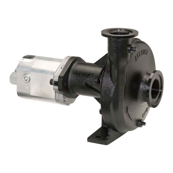
- Page 1 INSTRUCTION MANUAL ASIS WetSeal Technology MAX SERIES HYDRAULIC MOTOR DRIVEN CENTRIFUGAL PUMPS...
-
Page 3: Table Of Contents
Plumbing Diagram Pump Mounting Plumbing Suggestions Hydraulic Motor Features Hydraulic System Connections Hydraulic Motor Seals Regulating Hydraulic Flow Oasis™ WetSeal Technology Pump Maintenance Oasis™ WetSeal Maintenance Winterizing and Storage FMC-650-HYD Repair Instructions FMCWS-650-HYD Repair Instructions FMC-750F-HYD Repair Instructions FMC-855F-HYD Repair Instructions... -
Page 4: Plumbing Diagram
PLUMBING DIAGRAM Boom Valves Pressure Spike Valve Jet Agitator Anti-Vortex Tank Fitting Agitation Control Valve Pressure Gauge Agitation Valve Flow Meter Tank Valve Shut-off Valve Line Strainer Pressure Gauge A = 10 x hose diameter PUMP MOUNTING Ace centrifugal pumps are straight centrifugals and must be primed prior to operation. The word “primed”... -
Page 5: Plumbing Suggestions
¾ A pressure spike valve is recommended for use with Ace MAX series models. These models operate at pressures up to 160 psi (11 bar). A pressure spike is generated when the boom is turned off. -
Page 6: Hydraulic Motor Features
M SERIES HYDRAULIC MOTOR FEATURES Coasting Check - This internal feature is standard on all Ace hydraulic motors. It protects the motor seal from pressure spikes created by the flywheel effect of the impeller when the pump is turned off. Motor Ports M16, M22, and M25 Inlet &... -
Page 7: Regulating Hydraulic Flow
REGULATING HYDRAULIC FLOW TO MOTOR Warning: Failure to regulate oil flow may damage hydraulic motor. There are three types of hydraulic systems: 1) Load Sensing (LS) also called Pressure-Flow Compensating Closed Center, 2) Pressure Compensating Closed Center (PC), and 3) Open Center (OPEN). -
Page 8: Oasis™ Wetseal Technology
3. If a danger of freezing exists, drain all water from the pump casing by removing the lowest volute pipe plug. This will prevent casting breakage due to frozen liquid inside the pump. Note: Do not drain the barrier fluid from the seal reservoir on Oasis™ WetSeal models. -
Page 9: Oasis Wetseal Maintenance
2. Fill pump with recreational vehicle antifreeze to protect from corrosion and freezing. 3. If equipped with Oasis™ WetSeal, see Season End maintenance above. 4. If removing hydraulic hoses, insert plugs in motor ports to retain fluid and prevent contamination. -
Page 10: Fmc-650-Hyd Repair Instructions
FMC-650-HYD REPAIR REPAIR KITS & SEALS Ace pump repair kits include all shaft seals and O-rings required to repair the pump. Pump Model Standard Seal Severe Duty Seal FMC-650(F)(FS)-HYD Series RK-FMC-650 RK-FMCSC-650 Shaft Seal Only EDP# Recommended For BAC-7-650 water and general ag chemicals 40145 BAC-7SC-650 abrasive chemicals and fertilizers... - Page 11 ASSEMBLY INSTRUCTIONS 1. Install front snap ring into mounting frame bearing bore. 2. Press bearings onto shaft. Press one from each end until seated against step on shaft. 3. Install slinger over impeller end of shaft and push to bearing. 4.
-
Page 12: Fmcws-650-Hyd Repair Instructions
FMCWS-650-HYD REPAIR REPAIR KIT & SEAL Ace pump Oasis WetSeal repair kits include a dual shaft seal, O-rings, and barrier fluid to refill the seal reservoir. Pump Model Repair Kit EDP# FMCWS-650F(FS)-HYD Series RK-FMCWS-650 52722 ASIS Shaft Seal Only EDP#... - Page 13 ASSEMBLY INSTRUCTIONS 1. Install snap ring on shaft into second groove from impeller end. 2. Press bearing onto shaft from impeller end until seated against snap ring. 3. Install snap ring in groove on opposite side of bearing. 4. Install slinger on shaft over threaded end and push to step on shaft. 5.
-
Page 14: Fmc-750F-Hyd Repair Instructions
FMC-750F-HYD REPAIR REPAIR KIT & SEAL Ace pump Oasis WetSeal repair kits include a dual shaft seal, O-rings, and barrier fluid to refill the seal reservoir. Pump Model Repair Kit EDP# FMC-750F-HYD Series RK-FMC-750 52724 ASIS Shaft Seal Only EDP#... - Page 15 ASSEMBLY INSTRUCTIONS 1. Install snap ring on shaft into second groove from impeller end. 2. Press bearing onto shaft from threaded end until seated against snap ring. 3. Install snap ring in groove on opposite side of bearing. 4. Install slinger on shaft over threaded end and push to snap ring. 5.
-
Page 16: Fmc-855F-Hyd Repair Instructions
FMC-855F-HYD REPAIR REPAIR KIT & SEAL Ace pump Oasis WetSeal repair kits include a dual shaft seal, O-rings, and barrier fluid to refill the seal reservoir. Pump Model Repair Kit EDP# FMC-855F-HYD Series RK-FMC-855 52726 ASIS Shaft Seal Only EDP#... - Page 17 ASSEMBLY INSTRUCTIONS 1. Install snap rings on shaft into second and third grooves. 2. Press rear bearing (large) onto shaft from splined end until seated against snap ring. 3. Install snap ring in groove on opposite side of bearing. 4. Press front bearing (small) onto shaft from threaded end until seated against snap ring. 5.
-
Page 18: Hydraulic Motor Seal Kits
HYDRAULIC MOTOR REPAIR KITS Ace M Series hydraulic motors are high efficiency pressure balanced gear motors. The high efficiency design prevents replacement of some motor parts if damaged. See Ace Form # HYD-M SERIES for a listing of available replacement parts. The most common replacement part is the shaft seal which is listed in the table below for each motor model. -
Page 19: Motor Disassembly And Reassembly
MOTOR DISASSEMBLY & REASSEMBLY marking lines 1. Mark motor prior to disassembly at each section joint as shown in the diagram. These marks will serve as guides to reassemble motor components in original positions. 2. Remove 4 motor assembly bolts. Motors with socket head cap screws require a 9.5 mm or 3/8”... -
Page 20: Warranty
The warranty period is two years for pumps equipped with Oasis™ WetSeal Technology which requires proper maintenance of the seal chamber by the user as directed in the Instruction Manual. Products or parts found to be defective upon inspection at the factory will be repaired or replaced at our discretion.