
Related Manuals for Pleora Technologies iPORT SB-GigE-EV7520A

Summary of Contents for Pleora Technologies iPORT SB-GigE-EV7520A
- Page 1 PLEORA TECHNOLOGIES INC. iPORT SB-GigE-EV7520A External Frame Grabber User Guide Installing, Uninstalling, and Starting the Software Applications...
- Page 2 These products are not intended for use in life support appliances, devices, or systems where malfunction of these products can reasonably be expected to result in personal injury. Pleora Technologies Inc. (Pleora) customers using or selling these products for use in such applications do so at their own risk and agree to indemnify Pleora for any damages resulting from such improper use or sale.
-
Page 3: Table Of Contents
Further Reading ................3 About the iPORT SB-GigE-EV7520A External Frame Grabber ....... .5 SB-GigE-EV7520A Models . - Page 4 Technical Support ..............81 iPORT SB-GigE-EV7520A External Frame Grabber User Guide...
-
Page 5: About This Guide
Chapter 1 About this Guide This chapter describes the purpose and scope of this guide, and provides a list of complementary guides. The following topics are covered in this chapter: • “What this Guide Provides” on page 2 “Start Streaming Video” on page 2 •... -
Page 6: What This Guide Provides
Table 1: Documented Product Versions Product Release/version documented in this guide... SB-GigE-EV7520A 2.0.0 eBUS SDK and eBUS Player 5.1.10 iPORT SB-GigE-EV7520A External Frame Grabber User Guide... -
Page 7: Related Documents
Related Documents The iPORT SB-GigE-EV7520A External Frame Grabber User Guide is complemented by the following Pleora Technologies documents which are available on the Pleora Technologies Support Center at supportcenter.pleora.com: • eBUS Player Quick Start Guide and eBUS Player User Guide, available for Windows, Linux, and macOS •... -
Page 9: About The Iport Sb-Gige-Ev7520A External Frame Grabber
The following topics are covered in this chapter: • “SB-GigE-EV7520A Models” on page 6 • “Feature Set” on page 7 “Sony Block Camera Video Modes” on page 8 • “Key Sony Block Camera Features” on page 9 • About the iPORT SB-GigE-EV7520A External Frame Grabber... -
Page 10: Sb-Gige-Ev7520A Models
Gigabit Ethernet desktop network interface card (NIC) PoE power injector Ethernet cables eBUS SDK USB stick 1. Contains assembly #900-6166, which is not an orderable part. 2. Contains assembly #900-6169, which is not an orderable part. iPORT SB-GigE-EV7520A External Frame Grabber User Guide... -
Page 11: Feature Set
• Long reach: 100 m point-to-point, further with Ethernet switches Multicast • Enables advanced distributed processing and control architectures capability Mechanical bracket • Easy assembly with Sony block cameras *BayerGR8 pixel format not supported for 1080i 50/59.95/60Hz. About the iPORT SB-GigE-EV7520A External Frame Grabber... -
Page 12: Sony Block Camera Video Modes
* If the camera is set to an unsupported video mode (for example, HD_1080p_60Hz, HD_1080p_59p94Hz, or HD_1080p_50Hz), it will be automatically configured to HD_1080p_25Hz upon connection to the SB-GigE-EV7520A. In this situation, it can take up to 25 seconds to connect to the SB-GigE-EV7520A. iPORT SB-GigE-EV7520A External Frame Grabber User Guide... -
Page 13: Key Sony Block Camera Features
DeviceReset CAM_Initialize Camera Resets the device to its power up state. DeviceTemperature CAM_TempInq Device temperature in degrees Celsius (C). DeviceTemperatureSelector Selects the location within the device, where the temperature will be measured. About the iPORT SB-GigE-EV7520A External Frame Grabber... - Page 14 Reports the number of events that were received from the Sony Block and discarded by the SB-GigE-EV7520A. The counter does not wrap around upon reaching its maximum value. EventInfraredCutFilterState No direct mapping Returns whether the Sony Block infrared cut filter is activated. iPORT SB-GigE-EV7520A External Frame Grabber User Guide...
- Page 15 Controls the exposure time (shutter) of the Sony Block. CAM_Shutter Direct ExposureTimeRaw CAM_ShutterPosInq, Controls the exposure time of the Sony Block, in raw units. CAM_Shutter Direct Focus CAM_FocusPosInq, Sets the focus position of the Sony Block. CAM_Focus Direct About the iPORT SB-GigE-EV7520A External Frame Grabber...
- Page 16 Controls the near focus speed of the Sony Block. This feature is not directly mapped to a particular Sony Block command, but determines which command is executed by the FocusNear feature. FocusStop CAM_Focus Stop Stops a near or far focus command. iPORT SB-GigE-EV7520A External Frame Grabber User Guide...
- Page 17 Resets the settings of the selected line or lines. MultiLineTitleDisplay CAM_MultilineTitle (On, Off) Activates the display of the selected line or lines. MultiLineTitleFontColor CAM_MultilineTitle Title Set1 Controls the font color of the selected line or lines. About the iPORT SB-GigE-EV7520A External Frame Grabber...
- Page 18 SB-GigE-EV7520A. SonyBlockModel CAM_VersionInq Reports the model of the Sony Block connected to the SB- GigE-EV7520A. SonyBlockModelID CAM_VersionInq Reports the model ID of the Sony Block connected to the Video Interface. iPORT SB-GigE-EV7520A External Frame Grabber User Guide...
- Page 19 GevGVCPPendingAck is set to True (Guru visibility is required). Otherwise an error can occur, since this feature takes longer to apply than others. ZoomDigital CAM_DZoomModeInq, Controls whether digital zoom is enabled. CAM_DZoom (On, Off) About the iPORT SB-GigE-EV7520A External Frame Grabber...
- Page 20 No direct mapping Controls the zoom out speed of the Sony Block. This feature is not directly mapped to a particular Sony Block command, but determines which command is executed by the ZoomOut feature. iPORT SB-GigE-EV7520A External Frame Grabber User Guide...
- Page 21 Stops a zoom in or zoom out command. * To send these Sony VISCA commands to the camera, use the SB-GigE-EV7520A serial interface. See “Accessing Sony VISCA Commands that are not Mapped to SB-GigE-EV7520A Features” on page 18. About the iPORT SB-GigE-EV7520A External Frame Grabber...
-
Page 22: Accessing Sony Visca Commands That Are Not Mapped To Sb-Gige-Ev7520A Features
Transcript section. CAM_Custom, Use the SB-GigE-EV7520A userset feature instead of CAM_Custom and CAM_Memory. CAM_Memory CAM_IDWrite Use the SB-GigE-EV7520A DeviceUserID feature instead of CAM_IDWrite. CAM_Power Power on/off the SB-GigE-EV7520A. iPORT SB-GigE-EV7520A External Frame Grabber User Guide... -
Page 23: Sb-Gige-Ev7520A Connections
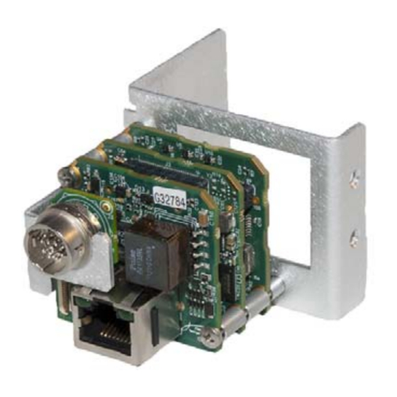
Chapter 3 SB-GigE-EV7520A Connections This chapter describes the SB-GigE-EV7520A connections. It includes pinouts for the GPIO, serial, and power connector. SB-GigE-EV7520A Shown with the camera bracket and GPIO bracket extension that are used in the development kit The following topics are covered in this chapter: •... -
Page 24: Connector Locations
Provides power and external signals, such as serial connector communication and GPIO, to the SB-GigE-EV7520A. Receives 10 V to 16 V of unfiltered DC input. For detailed information, see “Powering the SB-GigE- EV7520A” on page 32. iPORT SB-GigE-EV7520A External Frame Grabber User Guide... -
Page 25: Making Sb-Gige-Ev7520A Connections
Table 6: SB-GigE-EV7520A Connections (Continued) Location Type Description GPIO board 20-pin FFC Connects to the GigE PHY board with a 20-pin FFC cable. connector Adapter board 30-pin IDC Connects the Sony block camera to the SB-GigE-EV7520A. connector Important: The 30-pin coaxial board connector is very sensitive and can be damaged if used improperly. - Page 26 The metallic side of the cable ends should be oriented toward the circuit board in both cases. Camera Bracket 20-pin FFC connector (J9) 12-pin circular connector (J1) 20-pin FFC cable 20-pin FFC connector (J2) GPIO Board Assembly Continued on next page... iPORT SB-GigE-EV7520A External Frame Grabber User Guide...
- Page 27 Connect the 30-pin micro-coaxial cable to the 30-pin micro-coaxial connector (CN601) on the top of the block camera. Important: The 30-pin coaxial board connector is very sensitive and can be damaged if used improperly. See the important information in “Important Precautions for the 30-Pin Micro-Coaxial Connector” on page Connect the other end of the cable to the 30-pin IDC connector (J2) on the adapter board.
-
Page 28: Important Precautions For The 30-Pin Micro-Coaxial Connector
Note: If your images appear to have a purple hue, there could be a problem with the cable or connector. For more information, see “Images have a purple hue.” on page 71. iPORT SB-GigE-EV7520A External Frame Grabber User Guide... -
Page 29: 30-Pin Micro-Coaxial Connector Details
30-Pin Micro-Coaxial Connector Details Board Connector The board connector is made by KEL Corporation, model USL00-30L-C. The SB-GigE-EV7520A uses a similar board connector (KEL Corporation, model USL00-30L-A). Cable A cable is required to connect the FCB-EV7520A camera to the Pleora SB-GigE-EV7520A. The recommended cable is made by KEL Corporation, model USL20-30SS-015-CH which has a cable connector at each end. -
Page 30: Mounting The Power, Gpio, And Serial Connector To An Enclosure Backplate
Connect the GPIO board (12 holes) to the base pins of the 12-pin circular connector through the internal side of the backplate. Lock washer 12-pin circular connector Hex nut GPIO board Insertion Pins (soldered to GPIO board) 20-pin FFC cable Backplate of client-sourced enclosure Enclosure interior iPORT SB-GigE-EV7520A External Frame Grabber User Guide... -
Page 31: Power, Gpio, And Serial Pinouts: 12-Pin Connector On The Gpio Board
Assemble the 12-pin power, GPIO, and serial circular connector to the GPIO board by lining up the pins with the GPIO board. When oriented correctly, the tab on the 12-pin connector is aligned with the small white dot on the GPIO board, as shown in the following images. - Page 32 7. All GPIO inputs and outputs are connected to the level shifter SN74LVC2T45DCUR. For the exact logic levels and driving strength, see the data sheet at www.ti.com/lit/ds/symlink/ sn74lvc2t45.pdf. 8. Ferrite bead 0.2 A, 600 Ohm @ 100 MHz to the GND of the GigE PHY board. iPORT SB-GigE-EV7520A External Frame Grabber User Guide...
-
Page 33: Power, Gpio, And Serial Pinouts: 20-Pin Connector On The Gige Phy Board
9. Uses an 11 Ohm serial resistor. 10. Connected to the RS-232 transmitter/receiver MAX3221CPWR. For more information, see the data sheet at www.ti.com/lit/ds/symlink/max3221.pdf. 11. If you use an isolated enclosure box, it is recommended that you wire the shell of this connector to the ground on the GPIO board. - Page 34 14. For information about the status LED, see the description of the Power/Firmware LED in “Status LEDs” on page 34. 15. Not protected by a fuse; cannot be used as a power output. iPORT SB-GigE-EV7520A External Frame Grabber User Guide...
-
Page 35: Mapping Of Power, Gpio, And Serial Connector Pinouts
Mapping of Power, GPIO, and Serial Connector Pinouts This section describes how the pins of the 12-pin connector on the GPIO board are directly routed to the 20-pin connectors on the GPIO board and GigE PHY board. Table 9: 12-Pin Circular Connector to 20-Pin Connector Mapping Pin on the 12-pin Pin on the 20-pin Pin on the 20-pin... -
Page 36: Powering The Sb-Gige-Ev7520A
A resident common mode filter allows the input to be unfiltered, directly from a switching wall plug power supply. Maximum current is 1.5 A, limited by filtering circuitry. Ground Ground for VIN. Ground 0 V relative to other voltages on the SB-GigE-EV7520A. iPORT SB-GigE-EV7520A External Frame Grabber User Guide... -
Page 37: Power Consumption With The Sony Fcb-Ev7520A Block Camera
Power Consumption with the Sony FCB-EV7520A Block Camera Conditions: External power supply, room temperature. The FocusAuto feature is set to Off. Table 11: Power Consumption with External Power Supply External Data rate Average Streaming? Width Height Pixel format power (Mbps) power (W) HD_720p_30Hz video mode 10 V... -
Page 38: Status Leds
Off. No connection, 10 Mbps connection, or 100 Mbps connection. speed Green, on. 1 Gbps connection. *For information about the slide switches that are used to specify the firmware load, see “Changing to the Backup Firmware Load” on page 74. iPORT SB-GigE-EV7520A External Frame Grabber User Guide... -
Page 39: Thermal Requirements
Chapter 4 Thermal Requirements This chapter provides you with the information you need to ensure the optimal operating temperature for the SB-GigE-EV7520A. You should store the SB-GigE-EV7520A at temperatures between -40° to +85°C. Ambient and Junction Temperatures The following images and table outline the components that consume the largest amount of power on the SB-GigE-EV7520A, and that therefore are most likely to be heated beyond an optimal operating temperature. - Page 40 Ambient: Not specified Junction: Not specified Case: 0° to +95°C Power consumption: ~ 100-200 mW *Note: The FPGA board is the middle board, located between the GigE PHY board and the adapter board. iPORT SB-GigE-EV7520A External Frame Grabber User Guide...
-
Page 41: Signal Handling
Chapter 5 Signal Handling The SB-GigE-EV7520A includes a programmable logic controller (PLC) that lets you control external machines and react to inputs. By controlling your system using the PLC, you can make functional changes, adjust timing, or add features without having to add new hardware. PLC Programming Signals For an introduction to the PLC and for detailed information about how PLC signals are handled, see the iPORT Advanced Features User Guide, available on the Pleora Support Center at... - Page 42 Input, output No associated pin. Rescaler0Out Input No associated pin. Delayer0In Input, output No associated pin. Delayer0Out Input No associated pin. Event0 Input, output No associated pin. Event1 Input, output No associated pin. iPORT SB-GigE-EV7520A External Frame Grabber User Guide...
- Page 43 Table 15: PLC Signal Usage (Continued) PLC signal PLC equation usage Associated pin/signal Event2 Input, output No associated pin. Event3 Input, output No associated pin. ActionTrig0 Input No associated pin. ActionTrig1 Input No associated pin. Signal Handling...
-
Page 45: Bulk Interfaces
Chapter 6 Bulk Interfaces The SB-GigE-EV7520A has two bulk interface ports available for serial communication. The Bulk0 interface is reserved for communication and VISCA commands between the SB-GigE- EV7520A and the Sony FCB-EV7520A block camera. The interface is preconfigured for optimal settings;... - Page 46 * These features apply to Bulk1. ** These features only apply to Bulk0, which is reserved for communication with the Sony FCB-EV7520A block camera; the settings are preconfigured and should not be changed. iPORT SB-GigE-EV7520A External Frame Grabber User Guide...
-
Page 47: Installing The Ebus Sdk
44 • Installing the eBUS SDK You can install the Pleora Technologies eBUS SDK on your computer to configure and control your SB-GigE-EV7520A. The eBUS SDK includes: Pleora’s eBUS Player application, which allows you to control the SB-GigE-EV7520A parameters •... -
Page 48: Installing The Ebus Universal Pro Driver
After a moment the driver status changes. If you are installing a driver, the driver is installed across all network adapters on your computer. Close the eBUS Driver Installation Tool. You may be required to restart your computer. To see the versions of the installed drivers, click Help > About. iPORT SB-GigE-EV7520A External Frame Grabber User Guide... -
Page 49: Configuring Your Computer's Nic
Chapter 8 Configuring Your Computer’s NIC When using the SB-GigE-EV7520A and connected block camera, you may observe high data rates (above 800 Mb/s) that are close to the physical limit of Gigabit Ethernet (1000 Mb/s). This chapter provides guidance on how to configure your SB-GigE-EV7520A to maximize the performance of your system. The following topics are covered in this chapter: •... -
Page 50: Configuring The Nic For Communication With The Sb-Gige-Ev7520A
The instructions in this section are based on the Windows 7 operating system. The steps may vary depending on your computer’s operating system. To configure the NIC for optimal performance In the Windows Control Panel, click Network and Internet. Click Network and Sharing Center. iPORT SB-GigE-EV7520A External Frame Grabber User Guide... - Page 51 In the left-hand panel, click Change adapter settings. Configure the NIC for jumbo packets (more often referred to as jumbo frames) and set the NIC’s Receive Buffers (Receive Descriptors) to the maximum available value. Using jumbo packets allows you to increase system performance. However, you must ensure your NIC and GigE switch (if applicable) support jumbo packets.
-
Page 52: Calculating The Required Bandwidth
The interpacket delay is the time the SB-GigE-EV7520A waits before sending each packet of an image. If GevSCPD is set too high, then you may observe that the BlocksDropped (part of the Status statistics in the Image Stream Control dialog box) is increasing. iPORT SB-GigE-EV7520A External Frame Grabber User Guide... -
Page 53: Acquisition Frame To Skip
Acquisition Frame to Skip If the SB-GigE-EV7520A drops frames because of high bandwidth usage (close to 1 Gigabit), you can reduce the bandwidth by adjusting the AcquisitionControl\AcquisitionFrameToSkip feature. You can set this feature to 2 to skip two frames and then send one frame, resulting in one out of every three frames being sent, for example. -
Page 55: Connecting To The Sb-Gige-Ev7520A And Configuring General Settings Using Ebus Player
You can also configure the buffer options to reduce the likelihood of lost packets. eBUS Player is documented in more detail in the eBUS Player User Guide. The iPORT SB-GigE-EV7520A External Frame Grabber User Guide provides you with the eBUS Player instructions and overviews required to set up and configure general settings for the block camera and SB-GigE-EV7520A. -
Page 56: Confirming Image Streaming
Click Play to stream live images from the camera. After you confirm that images are streaming, click Stop. If images do not stream, see the tips provided in “System Troubleshooting” on page 69. iPORT SB-GigE-EV7520A External Frame Grabber User Guide... -
Page 57: Configuring The Buffers
Configuring the Buffers You can increase the buffer count using eBUS Player to make streaming more robust. A high number of buffers are needed in high frame rate applications, while a small number of buffers are needed for lower frame rates. Latency increases as the number of buffers increases. To configure the buffers Start eBUS Player. -
Page 58: Providing The Sb-Gige-Ev7520A With An Ip Address
LLA cannot be disabled and is always set to True. The SB-GigE-EV7520A can use the persistent IP address each time it is powered up as long as the IP address is valid and there are no IP address conflicts. iPORT SB-GigE-EV7520A External Frame Grabber User Guide... - Page 59 To configure a persistent IP address Start eBUS Player and connect to the SB-GigE-EV7520A. For more information, see “To start eBUS Player and connect to the SB-GigE-EV7520A” on page Under Parameters and Controls, click Device control. Under TransportLayerControl > GigEVision, set the GevCurrentIPConfigurationPersistentIP feature to True.
-
Page 60: Configuring The Sb-Gige-Ev7520A's Image Settings
If images are streaming, click the Stop button. Under Parameters and Controls, click Device control. Under ImageFormatControl, click a test pattern option (Off or iPORTTestPattern) in the TestPattern list. Close the Device Control dialog box. iPORT SB-GigE-EV7520A External Frame Grabber User Guide... - Page 61 To change the pixel format Start eBUS Player and connect to the SB-GigE-EV7520A. For more information, see “To start eBUS Player and connect to the SB-GigE-EV7520A” on page If images are streaming, click the Stop button. Under Parameters and Controls, click Device control. Under ImageFormatControl, set the PixelFormat feature to a color format.
-
Page 62: Implementing The Ebus Sdk
You can create your own image acquisition software for the SB-GigE-EV7520A. Consult the following guides for information about creating custom image acquisition software: eBUS SDK API Quick Start Guides, available for C++, .NET, Linux, and macOS • • eBUS SDK API Help Files iPORT SB-GigE-EV7520A External Frame Grabber User Guide... -
Page 63: Network Configurations For The Sb-Gige-Ev7520A
Chapter 10 Network Configurations for the SB-GigE-EV7520A After you have connected to the SB-GigE-EV7520A and provided it with a unique IP address on your network, you can configure it for either unicast or multicast. The following topics are covered in this chapter: •... -
Page 64: Unicast Network Configuration
Power supply or, if using Power over Ethernet, a PoE NIC, PoE switch, or PoE injector • GigE switch (optional) • CAT5e or CAT6 Ethernet cables • Desktop computer or laptop with eBUS SDK installed iPORT SB-GigE-EV7520A External Frame Grabber User Guide... -
Page 65: Sb-Gige-Ev7520A Configuration - Unicast Network Configuration
SB-GigE-EV7520A Configuration — Unicast Network Configuration After you have connected and applied power to the hardware components, use eBUS Player to configure the SB-GigE-EV7520A. To configure the SB-GigE-EV7520A for a unicast network configuration Start eBUS Player. Click Tools > Setup. Under eBUS Player Role, click Controller and data receiver. -
Page 66: Multicast Network Configuration
Compatible display monitor • Cable to connect the vDisplay HDI-Pro External Frame Grabber to the display monitor • GigE switch • CAT5e or CAT6 Ethernet cables Desktop computer or laptop with eBUS SDK installed • iPORT SB-GigE-EV7520A External Frame Grabber User Guide... -
Page 67: Configuring The Devices For A Multicast Network Configuration
Connecting the Hardware and Power The following procedure explains how to connect the power, network, and data cables to the vDisplay HDI-Pro External Frame Grabber and SB-GigE-EV7520A. To connect the network cables and apply power Connect one end of a CAT5e/CAT6 cable to the Ethernet connector on your computer’s NIC. Attach the other end to an available port on the GigE switch. - Page 68 Set GevSCDA to a multicast address (for example, 239.192.1.1). Close the Device Control dialog box. Now, configure the SB-GigE-EV7520A, as outlined in “To configure the SB-GigE-EV7520A for a multicast network configuration” on page 65. iPORT SB-GigE-EV7520A External Frame Grabber User Guide...
- Page 69 To configure the SB-GigE-EV7520A for a multicast network configuration Start an additional instance of eBUS Player. Click Tools > Setup. Under eBUS Player Role, click Controller and data receiver, as shown in the following image. Under GigE Vision Stream Destination, click Multicast and enter the IP address and port number. The address and port must be identical to that configured for the vDisplay HDI-Pro External Frame Grabber in step 8 and 9 of “To configure the vDisplay HDI-Pro External Frame Grabber for a...
- Page 70 Under TransportLayerControl > GigEVision, ensure that the port in the GevSCPHostPort field and the multicast IP address in the GevSCDA field are correct. They are configured automatically to the values set in step 4 of this procedure. Close the Device Control dialog box. iPORT SB-GigE-EV7520A External Frame Grabber User Guide...
- Page 71 Click Play to view the source image stream both on the computer and the display monitor. Network Configurations for the SB-GigE-EV7520A...
-
Page 73: System Troubleshooting
SB-GigE-EV7520A with the Sony block camera. It also shows you how to switch between the backup and main firmware loads. Not all scenarios and solutions are listed here. You can refer to the Pleora Technologies Support Center at supportcenter.pleora.com for additional support and assistance. - Page 74 Turn the test pattern on. Or, connect a video the image count (located video source is available source and ensure that Status > beside Stream at the bottom SonyBlockDigitalVideoClockPresent is True. of eBUS Player) does not increase when you click Play. iPORT SB-GigE-EV7520A External Frame Grabber User Guide...
- Page 75 Table 17: Troubleshooting Tips (Continued) Symptom Possible cause Resolution Images have a purple hue. The micro-coaxial cable may Ensure that the 30-pin micro-coaxial cable is not be connected properly or connected properly at both ends. the connector may be Try using a different 30-pin micro-coaxial cable. damaged.
- Page 76 Adapters for Best Performance Knowledge Base article, available on the Pleora Support Center. Also see “Calculating the Required Bandwidth” on page 48 and “Understanding the Effect of the Features on Bandwidth and Performance” on page 48. iPORT SB-GigE-EV7520A External Frame Grabber User Guide...
- Page 77 Table 17: Troubleshooting Tips (Continued) Symptom Possible cause Resolution Error occurs when saving or The SB-GigE-EV7520A has not Enable the Pending Acknowledge feature by loading a User Set in eBUS responded to the command setting the TransportLayerControl > Player or applications created within the specified amount of GigEVision >...
-
Page 78: Changing To The Backup Firmware Load
Pleora Support Center (supportcenter.pleora.com). FPGA Board SB-GigE-EV7520A External Frame Grabber FPGA Board To access the slide switch, peel back the small, protective plastic sheet that covers the slide switch. iPORT SB-GigE-EV7520A External Frame Grabber User Guide... -
Page 79: Reference: Mechanical Drawings And Material List
Reference: Mechanical Drawings and Material List This chapter provides the mechanical drawings, and also provides a list of connectors with corresponding manufacturer details. Three-dimensional (3-D) mechanical drawings are available at the Pleora Technologies Support Center. The following topics are covered in this chapter: •... -
Page 80: Mechanical Drawings
Mechanical Drawings The mechanical drawings in this section provide the SB-GigE-EV7520A’s dimensions, features, and attributes. All dimensions are in millimeters. Figure 4: SB-GigE-EV7520A Side View iPORT SB-GigE-EV7520A External Frame Grabber User Guide... - Page 81 Figure 5: SB-GigE-EV7520A GigE PHY Board Front with Dimensions Figure 6: SB-GigE-EV7520A with Bracket Mounting Screw Dimensions Reference: Mechanical Drawings and Material List...
- Page 82 Figure 7: SB-GigE-EV7520A with Brackets Top View Figure 8: SB-GigE-EV7520A with Brackets Top View iPORT SB-GigE-EV7520A External Frame Grabber User Guide...
-
Page 83: Adapter Board Mechanical Drawing
Adapter Board Mechanical Drawing The mechanical drawing in this section shows the positioning of the adapter board’s 30-pin IDC connector. All dimensions are in millimeters. Figure 9: Adapter Board Back View Material List The following table lists the connector details for the SB-GigE-EV7520A. Table 18: Connector Summary Location Description... -
Page 85: Technical Support
Chapter 13 Technical Support On the Pleora Support Center, you can: Download the latest software. • Log a support issue. • View documentation for current and past releases. • • Browse for solutions to problems other customers have encountered. • Get presentations and application notes.
Need help?
Do you have a question about the iPORT SB-GigE-EV7520A and is the answer not in the manual?
Questions and answers