Advertisement
Quick Links
Advertisement

Related Manuals for Smart Sensor Model:AS850


Summary of Contents for Smart Sensor Model:AS850
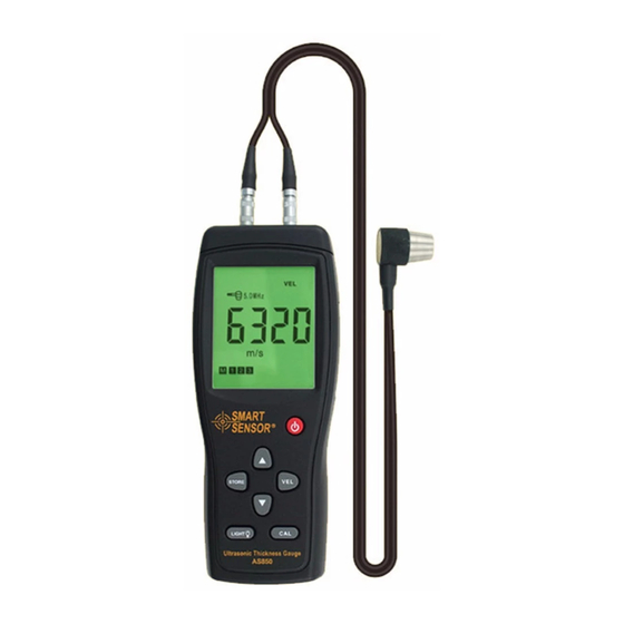
- Page 1 Model:AS850 Ultrasonic Thickness Gauge Instruction Manual...
- Page 3 Over warranty period, any repairing / maintenance will charge the fee on the buyer in standard rate by local distributor. The standard rate is not including the accessories which not packing Table of Contents in standard package(For example, abnormity transducer, lengthen lead-wire, special software) .
- Page 4 1.Introduction Do not use solvent/alcohol for cleaning which erode the cabinet & LCD Smart sensor AR850 ultrasonic thickness gauge is an intelligent hand- window, brush and sweep only with a moist cotton cloth. hold product, which adopts ultrasonic measuring principle, and is controlled by micro processor, provides quick and precise measurem- 6.4 Cleaning the sample block...
- Page 5 micrometer/caliber. 1.3 Standard packing & Parts description 1. Standard packing: 5.8 Abnormal reading Main unit-1PCS Transducer-2 PCS(Φ10mm 5MHz ,Φ10mm 2.5MHz) Coupling agent-1PCS(50ml) A seasoned operator should be capable to distinguish the abnormal reading, practically result from rusting, erosive recess surface / incorrect 4mmSample block-1PCS calibrate sample block/ the inner flaw of material.
- Page 6 4. Keypad diagram Take care for measurement while measuring the known rusting spot/ ON/OFF -- ON/OFF key suspicious area. or using sound insulation boardcelotex to locates the CAL -- Calibration key spot in different testing angles. VEL -- Sound velocity key STORE -- Measurement 5.3 Identify different velocity with vary material data stored key...
- Page 7 In most situations, using one referring block will get a satisfying keys to make a quick adjustment for the sound velocity measurement. This referring block must be the same material with /thickness,and a quick recall to the stored data. same thickness as the parts to be tested. The referring block should Coupling status indication: Observing the coupling icon to learn if be read out the thickness by micrometer.
- Page 8 The standard of selecting the angle between the crosstalk segregating 2.4 Working temperature condition board of the transducer and axis of the measured part is up to material Material thickness and sound velocity will change along with tempera- curvature. For bigger pipe diameters, choose vertical orientation between ture.
- Page 9 3.7 Low battery indication press “VEL” once more, the “VEL” and “m/s” will keep blinking, indentifying the When icon flashes, please replace the batteries for further mea- unit is on adjusting status. Then, increase or decrease the sound velocity to surement.
- Page 10 3.3 Thickness measurement 3.5 Data storage Put the coupling agent on the area to be measured to couple the trans- (1) Keep pressing STORE for 2 seconds to enter save thickness data mode, “ ” ducer with the hardware/workpiece, LCD will display the thickness LCD display THICKNESS, mm, icon with first memory unit.
Need help?
Do you have a question about the Model:AS850 and is the answer not in the manual?
Questions and answers