
Subscribe to Our Youtube Channel
Related Manuals for Hydro-Force Olympus Series

Summary of Contents for Hydro-Force Olympus Series
- Page 1 OLYMPUS Portable Extractor(s) Owner’s Manual For all currently manufactured Olympus models (2020 and newer) Hydro-Force Manufacturing 4282 South 590 West Salt Lake City, Utah, 84123 801-268-2673...
- Page 2 All users must read and understand this manual completely before operating the machine. Any questions on operating or servicing this unit should de directed to your nearest Hydro-Force distributor.
-
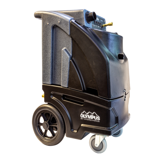
Page 3: Technical Specifications
Technical Specifications Olympus Dimensions Solution Tank 10 Gallons (approx.) Capacity Recovery Tank 10 Gallons (approx.) Capacity Dimensions 19.5” W x 27.25” D x 39.25” H (WxDxH) Wheels 12” Diameter Rear Wheels Casters 5” Diameter Front Casters Units at a Glance Model No. -
Page 4: Important Safety Information
Electric Components at a Glance Amp Draw Component Configuration Part # 115VAC, 60Hz 8.6 A with 2” orifice 2 Stage AV010 5.1 A with closed orifice Vacuum 10.4 A with 2” orifice 3 Stage AV14 6.7 A with closed orifice 100 psi AP120 1.0 A... - Page 5 • Solvent-based or water-based solutions containing solvents may damage the pump, hoses, and other components. Do not assume chemical compatibility. Contact your distributor or Hydro-Force if you have questions regarding the compatibility of your chemicals with the machine.
- Page 6 • High pressure hoses may rupture if worn or damaged. Do not use HP solution hoses if hose covering is cut, bulging, or otherwise damaged. Examine HP solution hoses daily and replace or repair hoses as needed. • Use defoamer to eliminate foam build-up during cleaning and prevent foam/moisture from entering vacuums.
-
Page 7: Setup And Operation
SET UP AND OPERATION: Electrical Specifications The Olympus is equipped with power cords and is designed to work with a 115VAC, 60hz, 15 or 20 amp circuits. These outlets are commonly found in homes and commercial buildings. Plug the two power cords into two outlets from different circuit breakers. Check that the Dual Circuit Indicator green light comes on, showing the two cords are on separate breakers. - Page 8 Connect Solution Hose Connect the high pressure solution hose to the Olympus using the female quick connect on the front of the switch plate. The solution hose is then attached to the cleaning tool. Connect Vacuum Hose Connect the vacuum hose to the unit using the 2” Flash Cuff connecter included on the vacuum hose supplied with the Olympus.
- Page 9 Pressure adjustment (if equipped) When the pump is on and primed, pressure will show on the gauge on the back of the Olympus. The pressure reading on the gauge will drop from its static state when the solution line is open and the tool is spraying.
-
Page 10: Shutdown Procedures
Heater The solution tank needs to be filled with the pump running and primed before the heater is switched on. Running the heater without water will damage the heater core. Allow the heater to heat up for about 5 minutes before starting to spray the tool. The heat delivered to the tool is dependent on two factors: •... - Page 11 Clean and inspect hoses Check tanks, hoses, filters and power cables for any signs of damage or wear Clean waste tank gate valve 1. Remove the filter screen from inside the solution tank and clean as needed. Clean Pump inlet 2.
- Page 12 Wiring Diagrams O200H, O500H O1200...
- Page 13 O3-200H O3-500...
- Page 14 O100...
-
Page 15: Troubleshooting
Troubleshooting Problem Cause Solution Building circuit breaker tripped. Reset breakers or move cords to other outlets Machine Faulty power cord Replace cord turning on - Check wiring & test switches - Repair as Faulty switches or internal wiring No power needed * Building circuit breaker tripped. - Page 16 Troubleshooting Continued Problem Cause Solution Building circuit breaker Building circuit breaker tripped. Reset breaker or tripped. Reset breaker or move move cord to other outlet cord to other outlet Vacuum Faulty power cord Replace cord Motor Not Faulty switch or internal Running wiring Check wiring &...
- Page 17 Parts List and Breakdown Olympus Sub-Assemblies - 17 -...
-
Page 18: Solution Tank Assembly
Solution Tank Assembly - 18 -... - Page 19 Solution Tank Assembly Balloon Part Number Description Configuration Olympus 2617-0922 Solution Tank Barb, 1/2" x 3/8" BR030 Elbow, 90, 3/8" BR284 Street Fitting Bulkhead NM5098 3/8” PP14- Strainer Acorn 806504 3/4" Kit Float Valve Pump Out NM5740 Assembly Elbow 90 1/2" Pump Out BR286 Nipple, 1/2"...
- Page 20 Waste Tank Assembly - 20 -...
- Page 21 Waste Tank Assembly Balloon Part Description Configuration Number 2618-0923 Waste Tank Switch Plate Assembly AH224 Flash Cuff 2" MPT PEA11 Gate Valve, 1-1/2" MNPT NM5712 Adapter 2" FPT x 2" Slip NM5725 Gasket, Stand Pipe NM5727 Adapter, 2" MPT x 2" Slip PA029 Pipe, 2", ABS...
-
Page 22: Switch Plate Assembly
Switch Plate Assembly Switch Plate Assembly Balloon Part Number Description Configuration Switch Mounting 2625-0718 Plate Decal, Olympus Switch Plate Switch Rocker NM5714 Single Screw, 1/4-20 x 1/2" NM5028 NM5066 Washer, 1/4" Flat Quick Connect 1/4" AH101B Elbow 45, 1/4" BR272 Street NM5751 Washer 1/2"... - Page 23 Auto Pump-Out Assembly - 23 -...
- Page 24 Auto Pump-Out Assembly Balloon Part Number Description Configuration SWITCH Pump Out NM5749 FLOAT PUMP LITTLE Pump Out NM5053 GIANT HOSE 3/4" Pump Out NM5056 WATER ADAPTER 3/4" MPT TO Pump Out BR319 GARDEN HOSE CAP GARDEN Pump Out BR325 HOSE Pump Out BR600 GASKET...
-
Page 25: Base Assembly
Base Assembly - 25 -... - Page 26 Base Assembly Balloon Part Number Description Configuration OLYMPUS 2616-0921 LOWER BODY NM5009 CORD 12/3 X 2' NM5038 STRAIN RELIEF NUT STRAIN NM5039 RELIEF WHEEL 12" - 1/2" NM5722 2626-0719 AXLE OLYMPUS WASHER 1/2" NM5125 FLAT CAP AXLE NM5010 NAUTILUS RE CASTER 5"...
-
Page 27: Vacuum Assembly
Vacuum Assembly - 27 -... - Page 28 Vacuum Assembly Balloon Part Number Description Configuration OLYMPUS 2614-0929 VACUUM MOUNT GASKET VAC PA010A MOTOR 5.7 VAC MOTOR 5.7" 2 2 Stage AV010 STAGE SCREW 1/4-20 x 2 Stage NM5135 3.00" VAC MOTOR 5.7" 3 3 Stage AV14 STAGE Screw 1/4-20 x 4.5" 3 Stage NM5131 SOCHD SS...
- Page 29 Pump and Heater Assembly - 29 -...
- Page 30 Pump and Heater Assembly Balloon Part Number Description Configuration NM5057 PUMP ASSEMBLY 1200 NM5048A PUMP ASSEMBLY 1606-5563 PUMP ASSEMBLY AP120 PUMP ASSEMBLY NM5034 SCREW 1/4-20 X 1" NUT 1/4-20 SS NM4261 NYLOCK WASHER 1/4" FLAT NM5066 NA2258 HOSE CLAMP 100, 200 1611-5533 HOSE CLAMP 500, 1200...
-
Page 31: Limited Warranty
If you are unable to determine the cause or solution to the problem contact your distributor or Hydro-Force for assistance. Hydro-Force warrants the rotational-molded tanks and base of the Olympus to be free from defects in material or workmanship for five years from the date of purchase.
Need help?
Do you have a question about the Olympus Series and is the answer not in the manual?
Questions and answers