Table of Contents
Advertisement
Quick Links
SAVE THESE INSTRUCTIONS
FOR FUTURE REFERENCE
Listed to standards:
UL-1738
ULC-S636 Type ''BH'' vent
Report #
INSTALLATION
INSTRUCTIONS
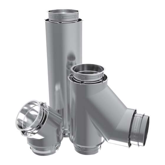
MODEL CAX1-(BC) (5" TO 36")
1" air Double Wall for Special Gas Vent
Category I, II, III, and IV Applications.
5" to 36" Diameter Vent for use on Positive, Neutral and Negative Pressures
up to 35" W.C.
This installation manual will enable you to obtain a safe, efficient and dependable
installation of this vent system. Please read and understand these instructions
before beginning your installation.
Do not alter or modify the components of this chimney system under any circum-
stances. Any modification of alteration of the vent system or approved accesso-
ries, including but not limited to the appliance it is connected to, may void the
warranty, listings and approvals of this system and could result in an unsafe and
potentially dangerous installation.
A. Examine all components for possible shipping damage prior to installation.
B. Proper joint assembly is essential for a safe installation. Follow these
instructions exactly as written: Check severeness of joints upon completion of
assembly.
C. This venting system must be free to expand and contract. This venting system
must be supported in accordance with these instructions.
D. Check for unrestricted vent movement through walls, ceilings, and roof
penetrations.
E. Different manufacturers have different joint systems and adhesives. Do not mix
pipe, fittings, or joining methods from different manufacturers.
FAILURE TO FOLLOW THESE INSTALLATION INSTRUCTIONS COULD CAUSE FIRE,
CARBON MONOXIDE POISONING, OR DEATH. IF YOU ARE UNSURE OF INSTALLA-
TION REQUIREMENTS, CALL THE PHONE NUMBER LISTED ON THE BACK OF THESE
INSTRUCTIONS.
A MAJOR CAUSE OF CHIMNEY RELATED FIRE IS FAILURE TO MAINTAIN REQUIRED
CLEARANCES (AIR SPACES) TO COMBUSTIBLE MATERIALS. IT IS OF UTMOST IM-
PORTANCE THAT THIS VENT SYSTEM BE INSTALLED ONLY IN ACCORDANCE WITH
THESE INSTRUCTIONS
PI HYBRIDCAX1 LS470 REV. 00 08-08-19
WARNINGS
1
Advertisement
Table of Contents

Related Manuals for Security Chimneys CAX1

Summary of Contents for Security Chimneys CAX1
- Page 1 INSTALLATION INSTRUCTIONS MODEL CAX1-(BC) (5" TO 36") 1" air Double Wall for Special Gas Vent Category I, II, III, and IV Applications. 5” to 36” Diameter Vent for use on Positive, Neutral and Negative Pressures up to 35” W.C. This installation manual will enable you to obtain a safe, efficient and dependable installation of this vent system.
-
Page 2: Table Of Contents
Introduction ..............page 2 Testing/ listing information ..........page 2 CAX1-(BC) double wall (5" TO 36") is a special stainless steel vent system Part numbers ..............page 3 for gas fired appliances listed as Category I, II, III, and IV in USA UL Effective length .............. -
Page 3: Part Numbers
(288°C) Table 1 - Minimum Clearances to Combustible for CAX1-(BC) Example: CAX1 36” length with inside diameter 14” made of SS 316 inner flue and SS 304 outer casting. CAX1 Auxiliary parts such as combination Roof Supports, Roof Thimble, Flashings, and Model Dia. -
Page 4: General Installation Requirements
• Maintain rated clearances to combustibles over the entire length of the vent system. Example: Model CAX1-(BC) 6” diameter section of 25 feet in length, weight in lb/ft = 4.1. Total length 4.1 x 25 = 102.5 lbs. • CAX1-(BC) -
Page 5: Support Methods And Height
Ø24 to Ø36 Ø5 to Ø22 Wall Support Heavy Duty (WSHD) Ø24 to Ø36 13' 6" Table 3 : Maximum Height Limits for each Type of Support for CAX1-(BC) 13' 9" 14' 3" 14' 6" GUYING AND BRACING Table 4: Support and Guide Spacing for Model CAX1-(BC). -
Page 6: Horizontal Installation Requirements
7. Unless CAX1-(BC) is installed in a fire rated shaft, a roof thimble and 1 ft. above ground or support is required when penetration fire rated floors, walls or ceilings. -
Page 7: Roof/Floor Penetration
Always check the appliance manufacturer’s instructions for proper drain 2” Minimum overlap requirements. Add sealant • CAX1-(BC) offers a range of tees and elbows that are built incorporating Termination a 2 degree slope, we recommend that you use these to generate your slope. •... -
Page 8: Condensate Drains
Doing so may result in dangerous icy conditions on surfaces near the drain and may cause damage to the vent system and the building exterior. Security Chimneys™ will NOT be held liable for any injury or property damage due to formation of ice. -
Page 9: Section B
SECTION B SPECIFIC INFORMATION MODEL CAX1-(BC) (5” TO 36”) TYPICAL INSTALLATION FOR CAX1-(BC) Finishing Cone ( FC) Heavy Duty WALL SUPPORT (WSHD) VARIABLE LENGTH (LV) Heavy Duty WALL GUIDE (WGHD) Heavy Duty WALL \�zz zz�� :zzzz p: z:z;�:z:z :zzzz� fr ZZ:ZZ 2j "lZ, ZZ:ZZ� � :zzzzzz � � �... -
Page 10: Guying And Bracing
TYPICAL INSTALLATION FOR CAX1-(BC) (5” TO 36”) MAXIMUM HEIGHT SEE TABLE 3 Figure 6 - Height with rigid bracing or guying option for CAX1-(BC) Figure 7- Maximum freestanding Height for CAX1-(BC) • If Dimension “H” exceeds the value In the Table 7 & 8, use bracing or cable guying to stabilize chimney section above the roof. -
Page 11: Joint Assembly
Tighten the screws of the band. O-ring to properly caulk. NOTE: Light tapping with a hammer all around the band while NOTE: Diameter of the CAX1-(BC) shown in pictures for the installation tightening bolts helps align and pull flanges together. assembly are smaller then reality. -
Page 12: Straight Sections
NOTE: Viton® caulking must be applied on each Variable Length (LV) access and drainage is needed (see Figure 9). and must be supplied by Security Chimneys. Sealant must be ordered separately (Not included in the LV assembly). 4. The drain coupling must be connected to a ”P” trap or approved container (supplied by others). -
Page 13: Installation Steps For Variable Length (Lv)
INSTALLATION STEPS FOR THE VARIABLE LENGTH (LV) Flange to flange length adjustment can range from 7”x 281/2” NOTE: If the flue is too long to fit into the adjacent section of duct without Step 1- Measure the distance X required for the variable length. See interfering with the flow path, it should be trimmed to desired flange Figure 13. - Page 14 Step 4 - Install the interior assembly between the two parts. Place the Step 9 -Slide down the retaining band on the double flanged sleeve to adjustable flanged band assembly toward the downstream section. mate their flanges and tighten the retaining collar. Step 5-Assemble the outlet end sliding innerwall to the outlet end section Step 10 -Then install the other V-band (BSI) over these flanges (like as a regular section (See JOINT ASSEMBLY section).
-
Page 15: Caps
CAPS Step 3 - Mate the flange of the outer casing with the flange of the out wall of the Tee section. TEE CAP (TC) Step 4 - Secure with the bigger V-Band (BSI) by tightening the retaining The Tee Cap provides access for cleaning and inspection. Usually on screw. -
Page 16: Offset
45 1/2 3 1/2 9 1/8 16 3/4 46 1/4 47 1/2 3 1/2 9 1/2 17 1/4 48 1/8 49 1/2 TABLE 7- Minimum Offset for Each Elbow for CAX1-(BC) Dimensions are in inches Figure 28: Eccentric Tapered Increaser (ETIN0) -
Page 17: Supports
SUPPORTS PLATE AND WALL SUPPORT Ventilated Anchor Plate (APV) Anchor Supports are designed to provide support to vertical sections and provide fixed-point support for horizontal sections. See Figure 29. NOTE: Rings installed at 90° to plates. Figure 31: Detail of the Ventilated Anchor Plate on a Framework. Supported duct sections in a vertical position must be braced with diagonal members or gussets to prevent deflection of the supported joint as shown in Figure 31. -
Page 18: Ventilated Anchor Plate With Length
26 to 36 Channel or Equivalent Channel or Equivalent TABLE 8 - Minimum Acceptable Size for Framework and Bracing for Model CAX1-(BC) VENTILATED ANCHOR PLATE WITH LENGTH (APVL) The APLV has a free anchor plate integrated on a length. It cannot be used has a fixed support for vertical or horizontal installation. -
Page 19: Heavy Duty Wall Support
Figure 38: WSHD Minimum Adjustment Figure 36: Step 3 of installation of APVL HEAVY DUTY WALL SUPPORT (WSHD) When attached to a non-combustible wall with brackets and struts, a Heavy Duty Wall Support makes up a fixed-point (See Figure 37). The clamp rings are installed with the splits 90°... -
Page 20: Heavy Duty Wall Guide
HEAVY DUTY WALL GUIDE (WGHD) FULL ANGLE RING (FAR) The Heavy Duty Wall Guide is designed to complement the Heavy Duty Wall Support (See Figure 40). It is used as a lateral guide to prevent the A Full Angle Ring is used as a guide to prevent the duct from flexing due duct from flexing due to lateral loading . -
Page 21: Location Of Supports
LOCATION OF SUPPORTS TEE SUPPORT The Tees must be supported properly to protect them from bending. It can Supports can be used in different combinations to secure grease duct in be done by means of Anchor Plate (AP), Anchor Plate with Length (APL) or place. -
Page 22: Flashings And Storm Collar
ROOF PENETRATION ELBOW SUPPORT Elbows are to be supported on one end with either a Ventilated Anchor STORM COLLAR (SC) Plate (APV), a Ventilated Anchor Plate with Length (APVL), or a Heavy The Storm Collar (SC) is used above the flashing for complete Duty Wall Support (WSHD). -
Page 23: Maintenance Instructions
NOTE: Maintain adequate spacing for expansion from the floor and the outer band (BSE) that is under the floor. As with all vents, the CAX1-(BC) vent system should be inspected at least annually for the presence of deposits or debris and any accumulation NOTE: If the maximum freestanding duct height above the Ventilated should be removed. - Page 24 2125 MONTEREY ST. • LAVAL, QC., CANADA • H7L 3T6 800-667-3387; www.securitychimneys.com Security Chimneys International Limited reserves the right to make changes at any time, without notice, in design, materials, specifications, prices. Consult your local distributor for chimney system code information.
Need help?
Do you have a question about the CAX1 and is the answer not in the manual?
Questions and answers