Table of Contents
Advertisement
Quick Links
Advertisement
Table of Contents

Related Manuals for PCB Piezotronics IMISensors Echo 670A01


Summary of Contents for PCB Piezotronics IMISensors Echo 670A01
- Page 1 Model 670A01 Echo® Wireless Vibration Sensor Installation and Operating Manual For assistance with the operation of this product, contact PCB Piezotronics, Inc. Toll-free: 800-959-4464 24-hour SensorLine: 716-684-0001 Fax: 716-684-3823 E-mail: imi@pcb.com Web: www.imi-sensors.com...
- Page 2 Assistance is needed to safely operate equipment PCB Piezotronics is an ISO-9001 certified company whose Damage is visible or suspected calibration services are accredited by A2LA to ISO/IEC Equipment fails or malfunctions 17025, with full traceability to SI through N.I.S.T.
- Page 3 CAUTION Refers to hazards that could damage the instrument. NOTE Indicates tips, recommendations and important information. The notes simplify processes and contain additional information on particular operating steps. The following symbols may be found on the equipment described in this manual: This symbol on the unit indicates that high voltage may be present.
- Page 4 PCB工业监视和测量设备 - 中国RoHS2公布表 PCB Industrial Monitoring and Measuring Equipment - China RoHS 2 Disclosure Table 有害物质 镉 汞 铅 (Pb) 六价铬 (Cr(VI)) 多溴联苯 (PBB) 多溴二苯醚 (PBDE) 部件名称 (Hg) (Cd) 住房 PCB板 电气连接器 压电晶体 环氧 铁氟龙 电子 厚膜基板 电线 电缆 塑料 焊接...
- Page 5 Component Name Hazardous Substances Lead (Pb) Mercury (Hg) Cadmium (Cd) Chromium VI Polybrominated Polybrominated Compounds Biphenyls (PBB) Diphenyl Ethers (Cr(VI)) (PBDE) Housing PCB Board Electrical Connectors Piezoelectric Crystals Epoxy Teflon Electronics Thick Film Substrate Wires Cables Plastic Solder Copper Alloy/Brass This table is prepared in accordance with the provisions of SJ/T 11364.
- Page 6 ® Echo Wireless Vibration Sensor User’s Manual 41967 Rev E ECO#: 50473...
-
Page 7: Table Of Contents
Table of Contents FCC NOTICE ........................3 INDUSTRY CANADA (IC) NOTICE ................3 ANATEL NOTICE (Applies to Model 670A01 only) ............3 HAZARDOUS AREA USE ....................4 Introduction ......................... 5 Proper Handling ........................5 Cap Material and Chemical Compatibility ................. 6 Magnet Switch and LED Status Indicator ................ -
Page 8: Fcc Notice
FCC NOTICE FCC ID: ZOC-IMI670A01 This device complies with part 15 of the FCC Rules. Operation is subject to the following two conditions: (1) This device may not cause harmful interference, and (2) this device must accept any interference received, including interference that may cause undesired operation. -
Page 9: Hazardous Area Use
HAZARDOUS AREA USE Warning- Explosion Hazard- Do Not Disconnect or connect while circuit is live unless area is known to be non-hazardous. Batteries must not be changed unless area is known to be Non-Hazardous. Do not open when an explosive atmosphere may be present. Substitution of components may impair suitability for Class I, Div 2. -
Page 10: Introduction
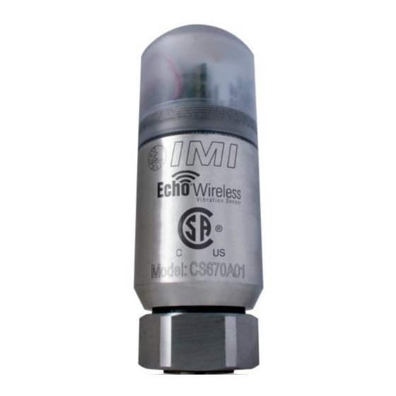
Introduction ® The Echo Wireless Vibration Sensor, Model CS670A01, is a standalone, battery powered, wireless, industrial vibration sensor. Its primary function is to monitor the vibration of machinery in condition monitoring and predictive maintenance applications. The sensor’s measurements are optimized to be sensitive to most common machinery faults such as unbalance, misalignment, looseness, bearing faults and gear faults. -
Page 11: Cap Material And Chemical Compatibility
Cap Material and Chemical Compatibility The sensor cap is made from a translucent polycarbonate material. This material was chosen because it is tough, allows the transmitted RF signal to radiate out of the sensor, permits visual feedback provided by the imbedded blue status LED, and reduces the passage of ultraviolet (UV) rays. -
Page 12: Magnet Switch And Led Status Indicator
Magnet Switch and LED Status Indicator ® The Echo Wireless Vibration Sensor has a magnetic switch located inside the sensor that is used to activate and deactivate the sensor. Hold a strong magnet next to the sensor housing at the location indicated on the housing, see figure below, to operate the switch. The blue LED light should begin blinking quickly within about 4 seconds. -
Page 13: Programming The Echo Wireless Vibration Sensor
® Programming the Echo Wireless Vibration Sensor Programming ® The Echo Wireless Vibration Sensor can be programmed with a computer running the ® Echo Monitoring Software through a serial port. While this is a serial port in the sensor, a micro USB connector is used in order to fit into the small space. A special (optional) ®... -
Page 14: Connect To The Sensor With The Echo® Monitoring Software
Connect to the Sensor with the Echo® Monitoring Software ® Launch the Echo Monitoring Software. You should see a screen similar to the one below. Click on Configuration on the menu bar. You should see a screen similar to the following, ®... - Page 15 You should see the following selections on the next screen. Click on ‘I want to add | ® update | view and Echo Sensors parameters’, then click on Next > at the bottom of the screen. Select the receiver where data from this specific sensor should be sent. This also, by default, specifies the database where data from this sensor will be stored.
- Page 16 ® When the following screen is displayed, make sure the Echo Programming Cable is connected to the computer, then; connect the micro USB connector to the sensor. After the blue LED blinks 5 times, click OK. The following connection window will appear. Select the appropriate COM port and ®...
-
Page 17: Factory Defaults
The green bar should illuminate indicating the connection has been made. The fields to the right of the window will populate with the current programmed parameters. Factory Defaults The factory defaults are defined below unless otherwise specified. See the explanation of the parameters below. -
Page 18: Transmission Interval
Transmission Interval: The Transmission Interval is the time between transmissions of measured data. The factory default is 8 hours. That means the sensor will “wake up” and make a measurement every 8 hours (3 times per day). At the default 8-hour transmission interval, the primary lithium-thionyl chloride (Li-SOCl ) batteries are expected to last in excess of 5 years. -
Page 19: Saving Changes To The Echo ® Sensor
® Saving Changes to the Echo Sensor ® Click the Set button next to each field to be updated to program the value in the Echo Sensor. To verify the programming when all changes have been made, click the Read Parameters button. -
Page 20: Mounting
Mounting ® The Echo Wireless Vibration Sensor should be stud mounted on a clean, flat surface. It is not recommended to mount the sensor with a magnet due to the size and mass of the sensor. The correct mounting torque for the sensor is 3 to 5 ft-lb (4 to 7 N-m). It is also a good idea to put a small amount of silicon grease on the bottom of the sensor before mounting. -
Page 21: Battery Pack
Battery Pack WARNING Do NOT attempt to recharge batteries Do NOT heat batteries above 212 °F (100 °C) Do NOT attempt to replace with standard AA size batteries. They will not work. ® Note: The Echo Sensor uses two 3.6 V, A-size (not AA) primary lithium-thionyl chloride (Li-SOCl ) high energy density, bobbin cell batteries in series that are NOT rechargeable. -
Page 22: Battery Replacement Instructions
Battery Replacement Instructions 1. Remove cap 2. Unplug and remove battery pack 3. Remove O-ring and battery securing foam 4. Place the new O-ring on the housing 5. Place grease completely around the O-ring 6. Place grease on and around the barb on the inside of the cap... - Page 23 7. Place the battery securing foam on the barb in the cap 8. Plug in the new battery cap and place the battery pack in the housing 9. Screw cap onto the housing a. Make sure that the foam is centered on top of the batteries. b.
- Page 24 Model Number Revision: D ECHO® WIRELESS VIBRATION SENSOR 670A01 ECN #: 47051 Performance ENGLISH OPTIONAL VERSIONS RMS Velocity Frequency Range(± 3 dB) 4 to 2300 Hz 4 to 2300 Hz Optional versions have identical specifications and accessories as listed for the standard model except where noted below.
- Page 25 PCB Piezotronics Inc. claims proprietary rights in REVISIONS the information disclosed hereon. Neither it nor any reproduction thereof will be disclosed to others DESCRIPTION without the written consent of PCB Piezotronics Inc. UPDATED TITLE 50473 1.66 [42.0] 4.4 [112] .87 [22.1] 1.50 [ 38.1]...
Need help?
Do you have a question about the IMISensors Echo 670A01 and is the answer not in the manual?
Questions and answers