Advertisement
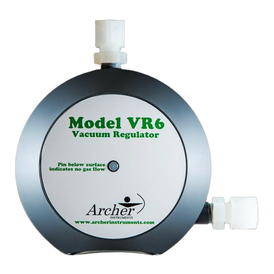
Model VR6 Vacuum Regulator
Installation, Operation & Maintenance
General:
All Archer Instruments chlorination systems are carefully designed and tested
for years of safe, accurate field service. All Archer Instruments chlorination systems are
carefully tested prior to shipment. All Archer Instruments products are made of the finest
materials. To ensure best operation, read these instructions carefully and completely and
store them where all maintenance personnel will have access to them.
Safety:
When working with chlorine, always use caution and follow applicable safety procedures.
General safety considerations:
* Store chlorine separately from ammonia.
* When using chlorine, avoid locations that expose the cylinder and equipment to direct
sunlight.
* Do not apply heater or heat source directly to chlorine cylinders.
* 150lb (upright) cylinders: Always keep cylinders upright and ensure the steel valve cap is
in place when moving cylinders. Once cylinder is in place, a safety chain should be used to
secure the cylinder.
* Ton Containers: Use appropriate handling equipment when moving ton containers. When
readying ton container for use, ensure valves are aligned vertically. The top valve accesses
gaseous chlorine and the bottom valve accesses liquid chlorine. The bottom valve should
never be touched unless your system employs a chlorine heat exchanger (evaporator)
designed expressly for use with liquid chlorine. When drawing gas from ton containers an
appropriate ton container adapter and drip leg must be used (also available from Archer).
Advertisement
Table of Contents

Subscribe to Our Youtube Channel
Related Manuals for Archer VR6


Summary of Contents for Archer VR6
- Page 1 All Archer Instruments chlorination systems are carefully designed and tested for years of safe, accurate field service. All Archer Instruments chlorination systems are carefully tested prior to shipment. All Archer Instruments products are made of the finest materials. To ensure best operation, read these instructions carefully and completely and store them where all maintenance personnel will have access to them.
- Page 2 1) Carefully inspect the cylinder valve outlet surfaces and vacuum regulator inlet capsule surfaces for damage or debris prior to installation. 2) Note that the inlet port on the VR6 regulator ships with a filter cartridge installed. Do not remove this filter, as doing so will bring on maintenance requirements.
- Page 3 3) If the remote meter is not mounted on the VR6, no further action is needed. 4) If the remote meter is installed on the VR6, adjust the remote meter’s rate valve knob until the desired feed rate is indicated on the graduated meter tube.
- Page 4 NEXT: The inlet assembly is a critical component in the safe function of the vacuum regulator. Improper handling or reassembly can result in dangerous leakage of chlorine gas. Archer recommends that only trained personnel or those familiar with vacuum regulator maintenance service the inlet assembly. To service the inlet assembly: 1.
- Page 5 15 1 VRA‐5015 Filter (100 PPD) * 1 SA‐210, VRA‐455 Silver Screen & Floss > 100 PPD 3 1 VRA‐600 Guide Pin 16 1 YMA‐100A Inlet Valve 4 1 OA‐VIT‐006 O‐Ring * 17 1 YPA‐101A Inlet Valve Seat * 5 1 DPA‐103 Double Diaphragm * 18 1 OA‐VIT‐010 O‐Ring * 6 1 FBA‐600 Front Body 19 1 SPA‐104 Inlet Spring 7 1 OA‐VIT‐156 O‐Ring 20 1 VRA‐601A Spring Retainer 8 1 BBA‐600 Back Body – 250 PPD & below 21 1 OA‐VIT‐009 O‐Ring * 1 BBA‐601 Back Body – 500 PPD 9 1 OA‐VIT‐332 O‐Ring 22 1 VRA‐56A Rear Diaphragm Plate 10 4 BTA‐123 Body Screws (Monel) 23 1 OA‐VIT‐029 O‐Ring * 11 1 OA‐VIT‐214 O‐Ring * 24 1 VRA‐269 Front Diaphragm Plate 12 1 YMA‐605A Back Plate 25 1 SPA‐100 Vent Spring 13 1 SAWS‐US3 Seal Adapter 26 2 TCA‐64 ¼” NPT x 3/8” tube 100 PPD * SAWS‐US3M Seal Adapter (Metal option) 1 TCA‐84 ¼” NPT x ½” tube 250 PPD 1 TCA‐108 ½” NPT x 5/8” tube 500 PPD Notes: * ‐ These parts are included in the Parts ‐ Maintenance Kit KT6‐10C Date: July 2016 ‐ Vent tube connector is always TCA‐64 (3/8”) Drawing: VR6 ...
Need help?
Do you have a question about the VR6 and is the answer not in the manual?
Questions and answers