Table of Contents
Advertisement
Advertisement
Table of Contents

Related Manuals for AQUARIUS ULTIMA


Summary of Contents for AQUARIUS ULTIMA
- Page 1 Instruction Manual v.1.1 Cooling Tower Controllers...
-
Page 2: Table Of Contents
Maintenance and Care of Sensors Accessories and Spare Parts Routine Testing Regular Inspection and Maintenance Electrical Wiring Connections System Configuration Turning ULTIMA controller ON Main Screen Setting System Preferences Advanced Settings Importing/Exporting Settings and Exporting Data Component Settings General Layout... -
Page 3: Warnings
Once maintenance is complete, the enclosure is to be closed and resealed. If the supply cord is damaged, it shall be replaced by Aquarius Technologies Pty Ltd or an authorized service agent to avoid a hazard. This appliance is not intended for use by young children or infirm persons unless they have been adequately supervised by a responsible person to ensure they can use the appliance safely. -
Page 4: Introduction
INTRODUCTION Ultima advanced cooling tower controllers model incorporates the following key features: • TDS/Conductivity Control • Inhibitor timer Control • Oxidizing biocide Control through ORP • Non-Oxidizing biocide control through timers • Single and Dual pH Control • Dispersant dosing Control •... -
Page 5: Installation Guidelines
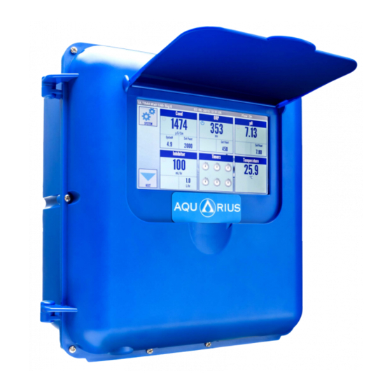
(e.g. metal fence or shed) and ideally not be in direct sunlight. The Ultima LCD screen must be covered by the flap lid for UV protection on all outdoor installation. A wall area of approx. 0.75 m. wide by 1.0 m. high is ideal for mounting your controller. -
Page 6: To Install
Assemble the inlet and outlet PVC valves on the sensor manifold. Remove the protective cap and fit the pH/ORP probe and other probes into the manifold. Install the BLEED solenoid on the manifold and wire the power cable supplied from ULTIMA. (Never leave the bleed solenoid cable unplugged when turning ULTIMA ON) Connect a 20 mm line from the circulating pump discharge line, or system common discharge header, to the inlet of the manifold. -
Page 7: Accessories And Spare Parts
• TUBEDISCHARGE (2 mt) Routine Testing The use of an Aquarius control system will automatically vary the dosages and maintain good conductivity, ORP and pH control, even where there are wide fluctuations in system load or demand. The principles of “Best Practice” and “Duty of Care” that are the responsibility of the system owner dictate that all systems should be routinely serviced and tested chemically and the results logged. -
Page 8: Electrical Wiring
Only Safety Extra Low Voltage (SELV) is supplied to the accessible circuit boards inside the enclosure. Sensors may be maintained while the controller is powered. CAUTION: Only a certified electrician or Aquarius Approved Service Technician may remove the protection cover to access the hazardous voltage area. It is required to disconnect the controller from the supply before removing the cover or performing any electrical work, including unplugging and/or replacing SELV circuit boards such as the Motherboard or Probeboard. -
Page 9: Connections
Connections The motherboard is located on the internal side of the front controller lid. The diagrams below show the connections to the Ultima controller motherboard circuitry: 1 – Power cable connector 2 – Probe-board power cable connector 3 – USB connector 4 –... - Page 10 The Probe-board is located above the protection cover on the bottom left hand corner of the controller. The diagrams below show the connections to the Ultima Probe-board circuitry: 1 – Power cable connector between Probe board and Motherboard 2 – BNC pH connector (if fitted) 3 –...
-
Page 11: System Configuration
System configuration The ULTIMA controller has a 7” touch screen and navigation is similar to that of any smart phone, PC monitor, GPRS navigator or other modern device. Operating the controller is done by touching the screen and navigating using your finger. The ULTIMA controller screen is covered with a protective film. -
Page 12: Main Screen
Main Screen The Main Screen display (Picture 5) Picture 5. MAIN Screen - Top bar with Connection Status, Date, Time, Flow ON/OFF parameters - Menu with icons on the left side of the screen. Icons are SYSTEM, LOCK SCREEN and NEXT - Six main parameters with Component information. - Page 13 The left-side Menu has the following icon boxes: ADVANCED, SAVE, IMPORT/EXPORT, RETURN. There are a further two icon boxes on the bottom right hand corner of the SYSTEM SCREEN: RESTORE DEFAULTS and REBOOT. ADVANCED icon is used for setting Date and Time, Language and Wi-Fi preferences. Date and Time should only be adjusted if the controller is not connected to the server.
-
Page 14: Advanced Settings
Advanced Setting When pressing the ADVANCED icon on the SYSTEM screen, an ADVANCED screen will appear (Picture 8). This screen has standard ANDROID options for setting Date and Time, Language and communication preferences. These preferences are to be set in accordance with standard procedures for ANDROID operating systems. -
Page 15: Component Settings
Component settings General layout: On the main screen (Picture 5) touch the component which you would like to configure. Most component screens have a similar structure: the left-side menu, Current value and Output active/inactive icon, the performance Chart in the middle of screen and Settings values on the right-hand. -
Page 16: Tds/Conductivity Configuration
CONTROL MODE: is provided to use either TDS or Conductivity mode for control. OUTPUT: Bleed solenoid is wired to output 5 on the power board. Any changes to the TDS/CONDYCTIVITY output must be made by Aquarius agents, certified electricians or an authorised service technician. -
Page 17: Orp Configuration
ORP Configuration On the main screen touch the ORP parameter box. The ORP screen will appear (Picture 13). Picture 13. ORP screen Setting values include SETPOINT, PUMP DUTY, MODE, ALARM MODE, ALARM RANGE, LOCKOUT DELAY and OUTPUT. Press each parameter to input a value or chose pre- determined options. -
Page 18: Ph Configuration
For PRECISE calibration the following calibration solutions are required: Part Number: AS4250 - 250 mV Part Number: AS5475 - 475 mV Press the SAVE icon for saving new settings after editing. A pop-up screen with confirmation of savings of new settings will appear. New settings will also be saved when pressing RETURN icon and returning to the MAIN screen. - Page 19 CALIBRATION icon allows the option of: QUICK and PRECISE calibration (Picture 18). Picture 18. pH CALIBRATION Screen Choose between QUICK calibration using a known pre-measured value or PRECISE calibration using calibration solutions. Follow the instructions on the screen to complete the calibration.
-
Page 20: Ph B Configuration
pH B Configuration This is used to control pH between two limits using Acid and Base. Push NEXT and pHB to configure this. For more details refer to pH configuration. Inhibitor Configuration On the main screen, touch the Inhibitor parameter box. The Inhibitor screen will appear to allow the user to set inhibitor settings. -
Page 21: Dispersant Configuration
Dispersant Configuration On the main screen, press NEXT. Now touch the Dispersant parameter box. The Dispersant screen will appear to allow users to set dispersant settings. (Pictures 22 and 23) Picture 22. Dispersant parameter box. Picture 23. Dispersant screen Setting values include MODE (including Disabled, Flow, Continuous, ORP, Bleed, and Inhibitor), PUMP SIZE, DOSE RATE and OUTPUT. -
Page 22: Timers Configuration
Timers Configuration On the main screen touch the TIMERS icon box. The TIMERS screen will appear (Picture 24). There are six timers available. Picture 24. TIMERS Screen Timers are used to run an output at a chosen time. Press one of the six TIMERS (Picture 25). Picture 25. -
Page 23: Outputs Configuration
WEEKS: The year is divided into 4 week cycles. The current week is shown as a highlighted box. Select which weeks this timer will be active for by pressing one, two, three or all four buttons. Active weeks are highlighted in Blue, inactive weeks are grey. Use Accessory Timers if you wish to control more than one output using the same timer. - Page 24 Outputs 5 to 7 will be used only on special orders hard wired to external relays or components. Output 8 will be used only on special orders hard-wired to an inbuilt 10-15A relay, for the use of directly switching chlorinators, large pumps etc. Outputs 9 to 13 are low power (can switch up to 50V/0.5A/10W peak) signals for use with switching dosing pumps or similar applications.
-
Page 25: Bio B Timer Example
Bio B Timer Example (Default) The secondary biocide timer Defaults are explained as a proper example for accessory timers Assume Bio B timer is set on Mondays at 08:00 for 1hr (Photo). The following accessory timers can be set: Accessory timer 1: Pre-Bleed for 15 minutes considering safety to avoid water waste Output: Conductivity Mode: Timer, Safety and Flow Dur: mm: 15... - Page 26 Accessory timer 2: Stop ORP (dosing oxidizing Biocide) 2 hours before dosing Bio B Output: ORP Mode: Timer, Safety and Flow Dur: hh: 2 Type: OFF Before Accessory Timer 3: Bleed Lock out for 4 hours considering safety for avoiding TDS build-up Output: Conductivity Mode: Timer, Safety and Flow Dur: hh: 4...
-
Page 27: Attachments
ATTACHMENT: Typical Installation Diagrams:...
Need help?
Do you have a question about the ULTIMA and is the answer not in the manual?
Questions and answers