Advertisement
Quick Links
————— Instruction Manual —————
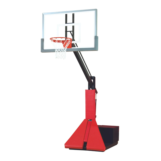
Max Portable/Adjustable Basketball System
Item
Qty
Description
A
1
Base Assembly
B
1
Left Hand Protection Pad
C
1
Right Hand Protection Pad
D
1
Center Protection Pad
E
1
Pole Protection Pad
F
2
4" Square U-Bolt
G
12
1/4" Flat Washer
H
4
1/2" Hex Nut
I
4
1/2" Lock Washer
J
12
1/4" x 1" Hex Bolt
K
1
Weight Cover
L
1
Vertical Pole
M
1
Horizontal Extension Arm
N
1
Horizontal I-Rod
Inspect all contents prior to installation. Report any missing parts to dealer immediately.
Read all instructions before proceeding.
Young players are at risk when they slam dunk on popular lowered height basketball systems.
Date: 05/05/17
Rev:7
MAX
BA853A, BA853G AND BA853GXL
PLEASE take responsibility for controlling dangerous activity.
B.A.
N.J.C.
File: \\bisonserver\publisher\instructions\BA853.pub
TM
P A R T S L I S T
Item
Qty
Description
O
3
Safety Shock
P
1
2000# Height Adjustment Crank
Q
7
Shock Spacer
R
2
1/2" x 6" Hex Bolt (pre-installed on system)
S
1
1/2" x 4 1/2 Hex Bolt
T
6
1/2" Lock Nut
U
2
1/2" x 8" Hex Bolt
V
1
1/2" x 4" Hex Bolt
W
1
Rim Height Indicator
X
1
Backboard Padding (if appropriate)
Y
1
Backboard (appropriate to system)
Z
1
Rim (appropriate to system)
AA
1
Backboard Mounting H-Frame (appropriate to system)
**
1
Hardware Supplied w/ Backboard Mounting H-Frame
Warning!
1
Customer Service
(800) 247 7668
Ref# 930151
Advertisement

Related Manuals for Bison MAX BA853A


Summary of Contents for Bison MAX BA853A
- Page 1 ————— Instruction Manual ————— Max Portable/Adjustable Basketball System Customer Service (800) 247 7668 BA853A, BA853G AND BA853GXL P A R T S L I S T Item Description Item Description Base Assembly Safety Shock Left Hand Protection Pad 2000# Height Adjustment Crank Right Hand Protection Pad Shock Spacer Center Protection Pad...
- Page 2 Warning! Assembly or operation without required 850# of weight (not included) in position under weight cover will result in unit tipping over. The roll around Base Assembly (A) is shipped pre- assembled and ready for installation of the 4" square pole system, backboard and goal.
- Page 3 6. Slide the Horizontal Extension Arm (M) through the opening in the Vertical Pole (L). Assemble with 1/2" x 6" Hex Bolt (R) and 1/2" Lock Nut (T). See Figure 3. 7. Install three Safety Shocks (O) using 1/2" X 8" Hex Bolts (U), 1/2"...
- Page 4 BA853A System BA853G and BA853GXL System **1/2"x 8" Hex Bolt **1/2"x 7" Hex Bolts **1/2"x 9"Hex Bolt **1/2" Lock Nut **1/2" Hex Nut **1/2" Lock Nuts **1/2" Lock Nut **Small 7/16" Spacers Figure 5A Figure 5B 12. Tighten all hardware installed from instructions #10 and #11 making sure that the Rim (Z), Backboard (Y) and the Backboard Mounting H-Frame (AA) are square to each other.
- Page 5 16. To attach the Rim Height Indicator Label (W), first crank up the unit until the top of the rim is 10' from the playing surface. Using a pencil, make a line on the Safety Shock (O) at the bottom end of the outer tube.