Table of Contents

Related Manuals for Ubiquiti EdgePower EP-24V-72W


Summary of Contents for Ubiquiti EdgePower EP-24V-72W
- Page 1 Package Contents EdgePower EP-24V-72W Mount Brackets (Qty. 2) Bracket Screws (Qty. 8) Wall Mount Screws (Qty. 2) Wall Mount Anchors (Qty. 2) Power Cord Create PDF in your applications with the Pdfcrowd HTML to PDF API PDFCROWD...
-
Page 2: Installation Requirements
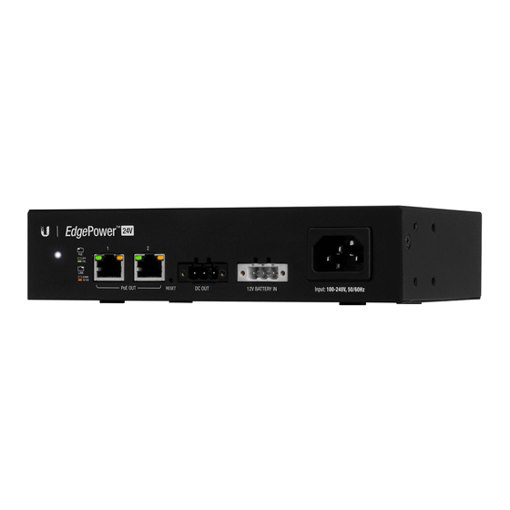
Power Cable with DC Jack Power Cable with Ring Terminals Installation Requirements For wall-mounting: Drill with 6 mm drill bit Phillips screwdriver Note: Although the cabling can be located outdoors, the EdgePower itself should be housed inside a protective enclosure. Hardware Overview Create PDF in your applications with the Pdfcrowd HTML to PDF API... - Page 3 System LED Flashing White Bootup in progress. Ready for use, not connected to Ubiquiti Network White Management System (UNMS™). Blue Ready for use, connected to UNMS. Steady Blue with Ready for use, unable to connect to UNMS, check Occasional Flashing connection to UNMS server.
-
Page 4: Hardware Installation
RJ45 switch ports support 10/100 Ethernet connections and 24V Passive Power over Ethernet (PoE) output. Reset Button To reset to factory defaults: 1. Disconnect power from the device. 2. Reconnect power while holding the Reset button. The port LEDs will repeatedly light up in sequential order (this takes approximately five seconds). -
Page 5: Connecting Power
The EdgePower can be mounted on a horizontal surface, mounted on a vertical surface, or mounted in a rack (rackmount accessory not included). WARNING: The EdgePower must not be stacked. Do not place it on top of another device. Do not place anything on top of the EdgePower. Connecting Power Use the included Power Cord to power the EdgePower. -
Page 6: Connecting Ethernet
Note: Only one power source can be used at any one time. With both power sources connected, the AC input will be used; the battery input defaults to backup. Connecting Ethernet WARNING: Before enabling PoE passthrough in the EdgePower Configuration Interface, ensure that the connected PoE device supports 24V Passive PoE. - Page 7 Connecting DC Output Create PDF in your applications with the Pdfcrowd HTML to PDF API PDFCROWD...
-
Page 8: Accessing The Configuration Interface
Accessing the Configuration Interface Access the EdgePower Configuration Interface to monitor status and power consumption, or to configure 24V Passive PoE and network settings. Note: The EdgePower is set to DHCP by default with a fallback IP address of 192.168.1.20. 1. - Page 9 2. Enter ubnt in the Username and Password fields. Click Login. The EdgePower Configuration Interface will appear. Customize additional settings as needed. For 24V Passive PoE configuration, refer to “Configuring PoE Settings”. UNMS Management You can manage your device using UNMS, which lets you configure, monitor, upgrade, and back up your devices using a single application.
- Page 10 WARNING: Before activating PoE, ensure that the connected device supports passive PoE and the supplied voltage. 1. In the EdgePower Configuration Interface, click the Power tab. 2. For the appropriate port, click to enable 24V Passive PoE. Create PDF in your applications with the Pdfcrowd HTML to PDF API PDFCROWD...
-
Page 11: Specifications
3. Click Save Changes. Specifications EP-24V-72W Dimensions 192 x 43.7 x 115 mm (7.559 x 1.72 x 4.528") Weight 650 g (1.43 lb) Interfaces Networking (2) 10/100 Mbps RJ45 Ports Management Ethernet In-Band PoE Output (2) 24VDC Passive PoE (Pins 4, 5+; 7, 8-) DC Output 24V, 3A Power Method... -
Page 12: Safety Notices
EP-24V-72W AC Input 100-240VAC, 50-60 Hz, Universal Input Battery Input DC Terminal Block Power Supply AC Input AC/DC 72W Battery Input 12VDC Lead Acid Battery* Max. Power Consumption System Output LEDs System Status RJ45 Data Ports PoE; Link/Activity ESD/EMP Protection Air: ±... -
Page 13: Electrical Safety Information
moisture. WARNING: Do not use this product in location that can be submerged by water. WARNING: Avoid using this product during an electrical storm. There may be a remote risk of electric shock from lightning. Electrical Safety Information 1. Compliance is required with respect to voltage, frequency, and current requirements indicated on the manufacturer’s label. -
Page 14: Limited Warranty
Limited Warranty ui.com/support/warranty The limited warranty requires the use of arbitration to resolve disputes on an individual basis, and, where applicable, specify arbitration instead of jury trials or class actions. Compliance Changes or modifications not expressly approved by the party responsible for compliance could void the user’s authority to operate the equipment. -
Page 15: Declaration Of Conformity
environment this equipment may cause radio interference. CE Marking CE marking on this product represents the product is in compliance with all directives that are applicable to it. WEEE Compliance Statement Declaration of Conformity Online Resources Create PDF in your applications with the Pdfcrowd HTML to PDF API PDFCROWD... - Page 16 © 2020 Ubiquiti Inc. All rights reserved. Create PDF in your applications with the Pdfcrowd HTML to PDF API PDFCROWD...
Need help?
Do you have a question about the EdgePower EP-24V-72W and is the answer not in the manual?
Questions and answers