Table of Contents
Advertisement
Quick Links
Introduction:
The SE Controls range of
control systems are built
and tested control panels
specifically for Smoke and/
or Environmental Ventilation
Systems and for use with SE
Controls supplied equipment.
They must not be used for any other
application or in conjunction with
other manufacturers' products without
prior consultation with SE Controls.
+44 (0)1543 443060
sales@secontrols.com
www.secontrols.com
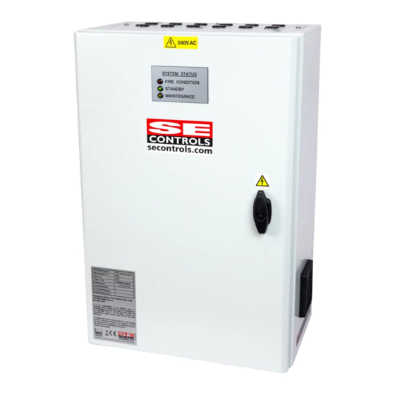
SHEVTEC PSU PANEL
Technical information and operating instructions
Installation of this equipment must
only be carried out by competent
and qualified persons.
The Installer and user are requested
to read, understand and retain
this information pack with the
panel for future reference.
This information pack must be
retained for future reference by
the client and be made available
for reference by persons installing,
servicing or modifying the panel.
Please keep these operating instructions for future reference and maintenance.
Application:
The SHEVTEC PSU Panel is a
powerful 24 Volt DC control
system designed for 2-wire
24V DC actuators in a smoke
control and/or environmental
ventilation system.
Operating from a 230VAC supply,
the SHEVTEC PSU Panel can deliver
up to 30/60/90 Amps to drive
24 Volt motorised actuators.
The SHEVTEC PSU Panel can be
mounted in a centralised plant
room location. Each SHEVTEC PSU
Panel can operate independently
or be linked to others to produce
a networked control system. The
networked control system in turn
can operate standalone or be linked
to a building management system.
Subject to technical modifications. Diagram is not binding.
Advertisement
Table of Contents

Subscribe to Our Youtube Channel
Related Manuals for SE Controls SHEVTEC 30A

Summary of Contents for SE Controls SHEVTEC 30A
- Page 1 SHEVTEC PSU PANEL Technical information and operating instructions Introduction: Application: The SE Controls range of The SHEVTEC PSU Panel is a Installation of this equipment must control systems are built only be carried out by competent powerful 24 Volt DC control and qualified persons.
-
Page 2: Table Of Contents
Contents Content Content Content 1. General 3. Connections 5. Installation, Commissioning Information and Fault finding 3.1. Power and control connections 1.1. General Safety Information 5.1 Fixing 3.2. Actuator connections 5.2 Low voltage 1.2. Health and Safety connections 3.3. Manual 1.3. Environment Control Points 5.3. - Page 3 Important Notices • This equipment has no • Failure to install the SE Controls accepts no mains on/off switch and is device in accordance liability for failure to intended for permanent with the manufacturer’s comply with the above statements or the connection only.
-
Page 4: General Safety
If recycling facilities are not locally available, 1.2. Health and Safety contact SE Controls who can arrange for recycling Electrical Safety: Warning 230 V AC mains supply and disposal of old electronic products. can cause death, serious injury or considerable material damage. -
Page 5: En12101-10:2005
1.9. Certification 1.6. Installation and Connection SE Controls hereby certify that the parts and services detailed hereon have been manufactured, Installation should be carried out by an inspected, tested and supplied in accordance with authorised, trained and competent electrician. -
Page 6: Specification
Specification 2.1. Device Overview Part numbers 30A SHEVTEC Panel FCS12001030 60A SHEVTEC Panel FCS12001060 90A SHEVTEC Panel FCS12001090 Dimensions 30A (600 X 400 X 250) (W x D x H) 60A (600 X 600 X 250) (W x D x H) 90A (800 X 800 X 300) (W x D x H) Mass Approx. -
Page 7: Psu Jumper Links
2.3. PSU Jumper links Jumper Jumper Detail Fitting a jumper link to the right hand side connects E and G together, with the link on the left hand side E and G are not connected. Fitting a jumper link to the right hand side connects M and 0 together, with the link on the left hand side M and 0 are not connected Fitting a jumper link to the right hand side connects C and E together, with the link on the left hand side C and E are not connected... -
Page 8: Pnc Fuse Chart
2.5. PNC Fuse Chart Fuse Function If open circuit 16 A 24V AC Input Not Used with SHEVTEC PSU. PER - Battery backed supply Standby LED goes out; PER supply terminals off; If external alarm connected will set off. 500 mA AUX - Auxiliary supply Not Used with SHEVTEC PSU. -
Page 9: Recommended
2.7. Recommended Cables Types Cabling For Minimum number of cores Recommended Cable Type Mains Supply Cable 2c + Earth FP Plus OS2 MCP 4c + Earth FP Plus 24VDC actuator 2c + Earth FP Plus OS2 Smoke detector 3c + Earth FP Plus OSlink Network Cable 2c + Earth... -
Page 10: Connections
In 5% step mode, each step is half a volt. The default controller settings have been chosen to cater for the majority of applications. If alternate settings are required please contact SE Controls. Please keep these operating instructions for future reference and maintenance. +44 (0)1543 443060 Subject to technical modifications. -
Page 11: Actuator Connections
The default mode of operation of these outputs is timed off, reversing polarity and is intended for use with linear and chain actuators. Locking catches, magnetic catches and rotary dampers can be used but require changes to the default settings of the controller by SE Controls. Output mode - timed off, reversing polarity... - Page 12 Reset button on the Manual Control Point is maintained. Note that the default Manual control point close mode can be changed by SE Controls to close fully in response to a brief press of the reset button. This mode change is only recommended where the activated vent is at least 2.5M above ground level to minimise finger trapping issues.
- Page 13 The MCP must be secured using the two fixing screws (Torx-T8) on the underside of the MCP module. Important; for instructions on installation and operation of the MCP refer to the user guide accompanying the device or contact SE Controls. Please keep these operating instructions for future reference and maintenance.
-
Page 14: Fire Alarm Inputs
3.4. Fire Alarm Inputs (FRA, ARA, SMK) All fire alarm input signals require a Normally Closed volt-free-contact which opens on fire signal initiation. The unit comes with all alarms hardware disabled via jumper links. To enable an alarm input, refer to the figure below. Each fire alarm input has different functionality. - Page 15 Intelligent Optical smoke detector ADA55000318 (Head) ADA45681245 (Base) This smoke detector is an exclusive S E Controls product and has been specifically designed to operate as part of SE Controls SHEVTEC systems. It has been marked as such to aid in identification for servicing and replacement.
-
Page 16: Day To Day
3.6. Day to Day Switch (DYO, DYC) Connecting terminals DYO and DYC to 0VP will open and close the vent in environmental ventilation mode. The default mode requires a spring centre 3 position switch having 2 normally open contacts. The actuator will only move whilst the input demand is in force and the total movement time in the requested direction is less than 18 seconds (default). -
Page 17: Thermostat (Tst)
3.7. Thermostat (TST) A simple volt free room thermostat can be used to operate the SHEVTEC PSU PANEL. The output contact is required to close when a demand to open a vent is required. When the demand is received, power is applied to the actuator outputs for 40 seconds in the open direction. When the demand is removed, power is applied to the actuator outputs for 40 seconds in the close direction. -
Page 18: Bms Analogue
By default, the input is configured to set the actuator position in 10% steps based on a scaling of 1V==10%,where 100% is the natural ventilation maximum run time (default 40 seconds). Other input scaling is available. Please refer to SE Controls for details. A second analogue input, AI2, having the same characteristics as AI1 is available. -
Page 19: Rain Sensor (Rns)
3.9. Rain Sensor (RNS) An input for the connection of a volt free normally open rain sensor is provided. When the contact closes, power is applied at the actuator outputs in the close direction for a period of 180 seconds. At the same time, a 180 second lock-out timer is started. -
Page 20: Network Connection
3.10. Network Connection (NTA, NTB, SCR) Connections NTA and NTB are used for network connection with network interface plug in boards. The use of these devices is outside the scope of this document. Please make reference to the individual product user manuals where necessary. Please keep these operating instructions for future reference and maintenance. -
Page 21: System Design
This is beyond the scope of • Is an MCP is needed on each OS2 and where it this document. If in doubt, consult SE Controls or might best be installed - The MCP control may approved agents who can give further guidance. -
Page 22: Installation, Commissioning And Fault Finding
Installation, Commissioning and Fault finding 5.1. Fixing Hold the panel against the surface to which it is to be fixed. Mark through the holes. Drill appropriate sized pilot/fixing holes and use plastic plugs/cavity fixings where appropriate. Use 4 10mm bolts to secure the panel firmly. •... -
Page 23: Mains Connection
5.3. Mains Connection Ensure the supply is securely isolated before connecting. Connect to the L; E and N screw terminals of the mains input. Ensure that it is fused to an unswitched mains outlet, using flexible 1.5mm² 3 core cable. Note that the terminal entries have openings suitable for use with up to 2.5mm2 cable. If no further wiring is to be connected at this time, remove the 13A fuse from the mains outlet to ensure the panel cannot be prematurely powered. -
Page 24: Battery Installation
5.4. Battery installation 5.5. First power-up tests. Once all other connection to the panel has Before powering up a system for the been made and the installation is ready first time, ensure the actuator and vent for commissioning, fit the batteries. installation is complete and operation of the actuators will not cause a hazard. -
Page 25: Basic Fault Finding
5.6. Basic Fault Finding If the system operates from mains power but when mains power is removed will not operate from batteries, it is possible that the batteries will require replacement. There are no user repairable parts. Fault rectification must only be carried out by authorised and competent persons. -
Page 26: Battery Replacement
5.7. Battery Replacement Batteries must always be replaced as a pair with batteries of equivalent construction, size and capacity (2 x 12V SLA 22.0AH). Replacing these with batteries that do not meet the charging voltage based on temperature (see graph) will invalidate the panel’s compliance to EN12101-10. -
Page 27: Wiring Schematics
Wiring Schematics 6.1. 30A PSU Panel C 10A AUXILIARY SUPPLY N E PE LED 2 LED 1 LED 4 LED 3 LED 6 LED 5 LED 8 LED 7 CLOSE OPEN LD10 CLOSE LD11 OPEN LD12 BATT CN11 CN12 WINK CN16 BATTERY 230v... -
Page 28: Psu Panel
6.2. 60A PSU Panel C 16A AUXILIARY AUXILIARY AUXILIARY SUPPLY SUPPLY SUPPLY LED 2 LED 2 LED 1 LED 1 LED 4 LED 4 LED 3 LED 3 LED 6 LED 6 LED 5 LED 5 LED 8 LED 8 LED 7 LED 7 LED 2... -
Page 29: Psu Panel
6.3. 90 PSU Panel LED 4 MAINS OK LED 3 CHARGING LED 2 CHARGED LED 1 BATT CONNECT LED 4 LED 4 MAINS OK MAINS OK LED 3 LED 3 CHARGING CHARGING LED 2 LED 2 CHARGED CHARGED LED 1 LED 1 BATT BATT... - Page 30 NOTES: Please keep these operating instructions for future reference and maintenance. +44 (0)1543 443060 Subject to technical modifications. Diagram is not binding. sales@secontrols.com www.secontrols.com...
-
Page 31: Sales@Secontrols.com
Lancaster House Wellington Crescent sales@secontrols.com Fradley Park, Lichfield www.secontrols.com Staffordshire WS13 8RZ Name & registered office: Loanguard Limited, Lancaster House, Wellington Crescent, Fradley Park, Lichfield, Staffordshire WS13 8RZ Company No.01468061 Vat No.377 5600 30 - SE Controls is a Registered Trademark...
Need help?
Do you have a question about the SHEVTEC 30A and is the answer not in the manual?
Questions and answers