Advertisement
Advertisement
Table of Contents

Related Manuals for Bang & Olufsen BeoAmp 2


Summary of Contents for Bang & Olufsen BeoAmp 2
- Page 1 BeoAmp 2 Type 9699 Installation Guide English - version 1.1...
-
Page 2: Important Safety Instructions
Warning Please adhere to all the following safety instructions before use: Important Safety Instructions Read these instructions. Keep these instructions. Heed all warnings. Follow all instructions. Do not use this apparatus near water. Clean only with dry cloth. Do not block any ventilation openings. Install in accordance with the manufacturer’s instructions. - Page 3 DANGER! No user serviceable parts inside. NOTICE! The Type label is placed on the bottom of BeoAmp 2. Safety symbol definitions: The lightning flash with arrowhead symbol within an equilateral triangle is intended to alert the user to the presence of uninsulated “dangerous voltage”...
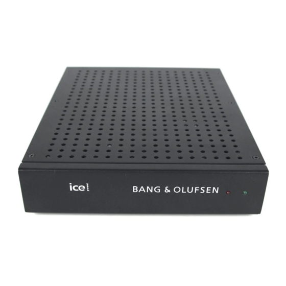
- Page 4 Introduction The BeoAmp 2 amplifier is a highly compact and light-weight solution with audiophile sound quality. Thanks to the class D technology, the amplifier has very low heat dissipation and is therefore perfectly suitable for installation in a rack system.
-
Page 5: Specifications
Specifications General Number of channels 2 channels Typical output power 150 W per Ch., 8 Ω (1%THD+N, f=1 kHz), @ 230 Vac Signal sense Audio input sense (Only on left channel) (Turns off after 13 minutes without a signal) External 12V trigger Power Link trigger Standby power consumption Less than 0.5 W... -
Page 6: Front Panel
Front Panel Status LED Status LED The front panel has a green and red status LED which indicate if the amplifier is turned on, in standby or in protection mode. Green Status Amplifier is turned on and ready for use Amplifier is in standby mode Protection mode Shutdown, either due to no AC mains voltage or because... -
Page 7: Audio Inputs
(Only pin 3, 4, 6, 7 and 8 are used.) *) The Line and Power Link loop out can be used for daisy chaining more BeoAmp 2 amplifiers. The signal input on the RCA input is hardwired to the RCA loop out connectors. -
Page 8: Speaker Outputs
AV receiver. The Signal Sense must be off for the 12V trigger to work. The 12V trigger input is hard wired to the 12V trigger output so the trigger signal can be used for other BeoAmp 2. Speaker outputs The speaker output terminals consist of a 4-pin terminal (Phoenix Contact MSTBVA 2.5/4-G-5.08 or similar) having two output terminals, each output... -
Page 9: Installation
Installation The amplifier has two different mounting options: a) in a standard 19” A/V rack and b) on a solid flat surface. Rack mount Detachable rack ears are included with the product for mounting in a standard 19” rack. Please see the illustrations below for rack possibilities. A single amplifier can be mounted using a regular short rack ear in one side and a long rack ear in the other side. - Page 10 Decision on loudspeaker wire size The higher the cross sectional area of a wire is, the lower the resistance in the wire is and thereby the signal loss. AWG 12 is the maximum size that can be placed in the connectors. The table below indicates the recommended maximum wire length.
- Page 11 Din Bang & Olufsen forhandler kan rådgive dig om den korrekte bortskaffelsesmetode i dit land. Deutsch (German) Mit diesem Symbol gekennzeichnete elektrische und elektronische Geräte, Bauteile und Batterien dürfen nicht in den normalen Haushaltsmüll gegeben, sondern müssen zum Schutz der Umwelt sämtlich getrennt eingesammelt und entsorgt werden.
- Page 12 Bang & Olufsen DK-7600 Struer Denmark 16-10...
Need help?
Do you have a question about the BeoAmp 2 and is the answer not in the manual?
Questions and answers