Table of Contents
Advertisement
Quick Links
ADJUSTABLE SWITCHES
SERIES
Installation & Operation Instructions
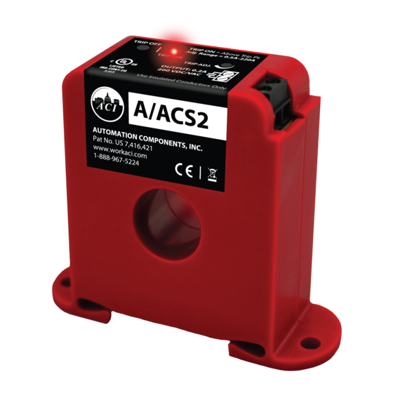
Part # A/ACS2, A/ACSX2, A/ASCS2, A/ASCS2-L, A/ASCSX2
PRECAUTIONS
• This product is not intended to be used for
Life or Safety applications.
• This product is not intended for use in any
hazardous or classi ed locations.
• The A/ACS2, A/ACSX2, A/ASCS2 & A/ASCSX2
Series Adjustable Switches must be used on
Insulated Conductors Only.
HIGH VOLTAGE
• Disconnect and lock out all power sources
before installation as severe injury or death
may result from electrical shock due to
contact with high voltage wires.
• Never rely on the Red LED to determine
whether power is present at the current
switch. At very low monitored input currents
the Red LED may not light to indicate the
current is above the trip point.
GENERAL INFORMATION
The Adjustable Current Switches are designed for
use in any AC current monitoring application in
which you are looking to monitor a particular piece
of equipment for equipment failure, preventative
maintenance, status, and electrical load status. The
current switches should be installed on the line side
of the power to the electrical equipment.
current switches are available in both solid and
split-core versions which also includes a Patented 35
mm Din Rail mounting foot for easy installation in
panel mount applications. The adjustable current
switches can be used to determine the run time of
your equipment as well as basic load trending applications where you want to know when how long your
piece of equipment runs when logging the contact closures on your building management system or PLC.
INSTALLATION
Ensure all installations are in compliance with all national and local electrical codes. Only quali ed
individuals that are familiar with codes, standards, and proper safety procedures for high-voltage
installations should attempt installation. The current switches will not require external power because the
power for the current switch is induced from the conductor being monitored.
Automation Components, Inc.
2305 Pleasant View Road | Middleton, WI 53562
Phone: 1-888-967-5224 | Website: workaci.com
FIGURE 1: DIMENSIONS
Solid-Core
2.36" (59.94mm)
1.03"
(26.16mm)
Split-Core
2.55" (64.69mm)
3.24" (82.23mm)
The
Page 1
Phone: 1-888-967-5224
Website: workaci.com
2.77"
(70.45mm)
2.87" (72.80mm)
3.35" (84.99mm)
2.77"
(70.35mm)
1.10" (28.02mm)
2.87" (72.77mm)
Version: 10.0
I0000788
Advertisement
Table of Contents

Related Manuals for aci A/ACS2


Summary of Contents for aci A/ACS2
- Page 1 ADJUSTABLE SWITCHES SERIES Phone: 1-888-967-5224 Website: workaci.com Installation & Operation Instructions Part # A/ACS2, A/ACSX2, A/ASCS2, A/ASCS2-L, A/ASCSX2 FIGURE 1: DIMENSIONS PRECAUTIONS Solid-Core • This product is not intended to be used for 2.36” (59.94mm) Life or Safety applications. • This product is not intended for use in any hazardous or classi ed locations.
- Page 2 The current switch may be mounted in any position FIGURE 2: OPENING A/SCS2 SERIES using the two #8 x 3/4” Tek screws and the mounting holes in the base, or snapped directly on to the 35mm DIN rail (See Figure 3). Leave a minimum distance of 1”...
-
Page 3: Wiring Instructions
WIRING INSTRUCTIONS ACI recommends the use of a two conductor 16 to 22 AWG shielded cable or twisted pair copper wire only, for all current switch applications. A maximum wire length of less than 30 meters (98.4 feet) should be used between the current switch and the Building Management System or controller. -
Page 4: Calibration Of Adjustable Trip Point
Go/No Go Current Switch as a Digital Input to your BAS/PLC Controller. Figure 6 (p.3) shows a Go/No/Go Current Switch in conjunction with a Contactor to control an exhaust fan. Note: The ACI Go/No Go Current switches are only rated at 0.2A @ 200 VAC/VDC and must use an additional Contactor if controlling motor/fans. -
Page 5: Product Specifications
0.2A @ 200 VAC/VDC WARRANTY The ACI Current Switch Series are covered by ACI’s Five (5) Year Limited Warranty, which is located in the front of ACI’S SENSORS & TRANSMITTERS CATALOG or can be found on ACI’s website: www.workaci.com. W.E.E.E. DIRECTIVE At the end of their useful life the packaging and product should be disposed of via a suitable recycling centre. - Page 6 NOTES Page 6 Automation Components, Inc. Version: 10.0 2305 Pleasant View Road | Middleton, WI 53562 I0000788 Phone: 1-888-967-5224 | Website: workaci.com...
- Page 7 NOTES Page 7 Automation Components, Inc. Version: 10.0 2305 Pleasant View Road | Middleton, WI 53562 I0000788 Phone: 1-888-967-5224 | Website: workaci.com...
- Page 8 Automation Components, Inc. 2305 Pleasant View Road Middleton, WI 53562 Phone: 1-888-967-5224 Website: workaci.com Page 8 Automation Components, Inc. Version: 10.0 2305 Pleasant View Road | Middleton, WI 53562 I0000788 Phone: 1-888-967-5224 | Website: workaci.com...
Need help?
Do you have a question about the A/ACS2 and is the answer not in the manual?
Questions and answers