Table of Contents
Advertisement
Quick Links
Advertisement
Table of Contents

Related Manuals for Hog Technologies Stripe Hog SK3000

Summary of Contents for Hog Technologies Stripe Hog SK3000
- Page 1 Operations Manual...
-
Page 3: Welcome
The information is intended as a guide and cannot cover every question you may have about your Stripe Hog and every operating situation. We encourage you to contact Hog Technologies ® for any additional information you might need. We provide first class support to our customers Caution and Warning Labels on High Pressure Pump for all of the equipment we sell. - Page 4 IMPORTANT: If you have questions about the equipment on your The terms and conditions of the Hog Technologies Stripe Hog, please contact the Customer Service Limited Warranty are outlined in the warranty Department.
-
Page 5: Safety Warnings And Instructions
BEFORE ATTEMPTING TO cONNEcT, OPERATE, OR REPAIR THIS EqUIPMENT, THOROUGHLY READ THESE INSTRUcTIONS AND ANY SAFETY wARNING OR INSTRUcTION PAMPHLETS INcLUDED wITH YOUR SHIPMENT. FOR ANY qUESTIONS cONcERNING SAFE OPERATIONS AND MAINTENANcE PROcEDURES, cONTAcT YOUR HOG TEcHNOLOGIES REPRESENTATIVE PRIOR TO USE. (772) 223-7393 OR (877) 964-7312 HOG TEcHNOLOGIES... - Page 6 IMPORTANT NOTE: Your Hog Technologies equipment uses internal combustion engines and flam- mable fuel. Every precaution has been taken by Hog Technologies to reduce the risks associated with possible injury and damage from fire or explosion, but your own precaution and good maintenance...
-
Page 7: Table Of Contents
3.1 SK3000 Tractor Operation ....................35 3.2 Tractor Hog Head & Hydraulic System ................38 3.3 Tractor Waterblasting ....................41 Section 4: Hog Technologies Hog Tools 4.1 Hog Tools (Optional) ....................43 4.2 Hog Tool Waterblast Systems ..................44 4.3 Hog Tool Vacuum Systems ....................44... - Page 8 SK3000 Specifications ......................91 Appendix D: Checklists Pre-Start Procedure ......................93 Startup Procedure ......................94 Shutdown Procedure ......................95 Freezing Conditions Shutdown .....................96 Appendix E: Spray Bar Configuration and Nozzles Nozzle Configurations ......................97 Appendix F: Hog Technologies Resources Stripe Hog Support Web Page ...................106...
-
Page 9: Safety Information
40,000 PSI (2,758 Bar). With system operating properly, set your pressure according to methods described by pump manu- Never Alter a Hog Technologies Product facturers instructions. Refer to the Pump oper- Do not alter any product without written consent ating manual for specifications and instructions. -
Page 10: Blasting Safety
Safety Information Be Prepared If the equipment malfunctions or a malfunction is suspected, immediately stop all blasting activity and relieve the pressure in the system before at- tempting any repair. Always follow manufacturer’s repair instructions. Notice: Use Only Thoroughly Trained Personnel to Perform Maintenance or Repairs Low Pressure Test Following repairs, operate the system at low pres-... -
Page 11: Nozzle Safety
Safety Information Start at Low Pressure OSHA’s Permissible Noise Exposure Always start blasting with the system at low pressure slowly increasing to operating pressure. 90 dB 8.0 hours Engage and disengage Ultra High Pressure (40 K) 92 dB 6.0 hours switch two times at operating pressure to check 95 dB 4.0 hours... -
Page 12: Hose Safety
Nozzle Flow Chart Safety Information Clogged Nozzles Stretched or abused hose can fail prematurely and unexpectedly, which could cause injury to If a nozzle appears clogged, immediately disen- personnel. Hoses that have been exposed to gage pump. Remove any clogged nozzles and excessive stretching or kinks should be removed replace with new nozzles. -
Page 13: High Pressure Fitting Safety
Safety Information Check Pressure Rating 1.5 High Pressure Fitting Safety Only Use high pressure hoses with an operating Fitting Ratings pressure rating of 36,000 - 40,000 PSI (2,482- Use high pressure fittings with a rating of 60,000 2,758 bar.) PSI (4,137 Bar.) Check Burst Rating Check Fittings Do not use a high pressure hose that does not... - Page 14 THIS PAGE WAS LEFT BLANK INTENTIONALLY...
-
Page 15: Sk3000 Systems
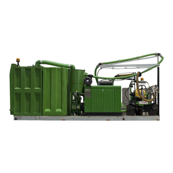
Section 2: SK3000 Systems SK3000 Skid Unit on these forms should be filled out completely and submitted to the dealer or manufacturer as 2.1 Skid Mounted Power System soon as possible. Overview The SK3000 is skid mounted and completely self The SK3000 skid system is designed to be used contained. -
Page 16: Sk3000 Engine And Power Take-Off
THROUGH BOLTS OF THE qUANTITY, are marked in the photo above. The lift points are SIZE AND RATING REcOMMENDED BY HOG TEcHNOLOGIES. also used to secure the unit to the truck chassis NEVER OPERATE THE TRUcK OR TRAILER IF THE UNIT IS NOT or trailer with chain binders. - Page 17 SK3000 Systems circuits from an overload. Gauges in the panel allow the operator to monitor engine RPM and important systems. Electronic engine controls monitor critical engine functions providing opera- tor warning alarms and/or engine shutdown to prevent costly engine repairs. The engine should be started when the SK3000 is on the job site, set up and ready to go to work.
-
Page 18: Primary Drive Belts
SK3000 Systems terblasting controls for your SK3000. To stop the engine: Turn the waterblasting systems OFF. Reduce the engine RPM to idle and disengage the PTO. Allow the engine to operate at idle speed for at least 5 minutes to allow internal temperatures to cool. -
Page 19: 12-Volt Dc Electrical System
SK3000 Systems Proper diesel engine operation requires a good supply of clean, dry diesel fuel. Improper fuel storage techniques, limited equipment usage, etc. can cause the fuel to become contaminated. Fuel Fill Periodically, it may be necessary to drain accu- mulating water and contaminated fuel from the Return Fuel Valve bottom of the fuel tank. -
Page 20: Sk3000 Onboard Hydraulic System
You also should not mix the size or brand of wet cell batteries. Always consult Hog Technologies or the engine manu- facturer before changing the type of batteries in your SK3000. -
Page 21: Sk3000 Waterblasting Systems
CAUTION THE BATTERY MUST BE PROPERLY cHARGED BEFORE OPERATING THE HYDRAULIc PUMP wHEN THE ENGINE IS Optional Hog Technologies HT500 Hog Pack NOT RUNNING. OPERATING THE HYDRAULIc PUMP FROM A BATTERY wITH A LOw cHARGE MAY LEAD TO A PUMP FAILURE. - Page 22 SK3000 Systems the Hog Head. When the Hog Pack is used, lever switches and knobs on the Waterblasting unit control the hydraulic functions of the equipment and the rotation of the spray bar. Refer to the Hog Tools section in this manual for more information on optional tools that require the HT500 Hog Pack.
- Page 23 SK3000 Systems Always monitor the water level in the clean water tank and make sure you have enough water for the intended shift. Never operate the engine when the water tank is low on water and always stop blasting and shut the engine down immediately when low water is observed.
- Page 24 SK3000 Systems pump are operating. The water flow to the packing should be checked at the beginning of each shift by monitoring the flow of water from each packing with the PTO dis- engaged and the engine at idle. There should be a noticeable flow of water from each packing.
- Page 25 SK3000 Systems High Pressure Pump, Pressure Gauge, PTO Engagement Handle and Manual Bypass Valve head to be immediately reduced to less than 100 PSI (7 Bar) at any time without causing damage to the high pressure lines and components. Maximum operating pressure for the UHP pump of 40,000 PSI (2,758 Bar) @ 6 gallons (22 Li- ters) per minute is achieved at maximum engine RPM.
- Page 26 Each manufacturer of the major UHP waterblasting the label on the rupture disc assembly or contact system components provides an information and Hog Technologies Customer Service for the correct operating manual with its product. It is extremely rupture disc rating for your equipment. Never...
- Page 27 SK3000 Systems WARNING HIGH PRESSURE wATER FROM SPRAY jETS OR RUPTURED HOSES cAN cAUSE SEVERE INjURY OR EVEN DEATH. ALwAYS BE SURE wORK AREA IS cLEAR OF PEOPLE, HANDS, FEET, ETc., BEFORE ENGAGING THE cLUTcH AND THE HIGH PRESSURE SwITcH FOR THE STRIPE HOG. High Pressure Hoses and Fittings The SK3000 waterblasting system operates at ultra high pressures of up to 40,000 PSI (2,758...
- Page 28 The performance ranges from least ag- rienced, nozzle selection becomes easier. You can gressive to most aggressive. also contact Hog Technologies Customer Service for assistance in selecting the proper spray bar Nozzles typically last 12-16 hours of blast time, and nozzle configuration for your job.
- Page 29 60,000 PSI (4,137 Bar.) We recom- mend that you only use nozzles, high pressure hoses and fittings supplied by Hog Technologies to ensure the nozzles and other components are compatible with your Ultra High Pressure Water- Typical Spray Bar Shield Installed blasting System.
-
Page 30: Sk3000 Vacuum System
Hog Head when attached to the tractor, Ground Hog or other Hog Technologies equipment. A filter located in the filter canister protects the blower from debris and a silencer mounted above blower reduces... - Page 31 SK3000 Systems Important: Make sure the drain valve is closed, the canister door seal is clean and the door is properly latched before operating the vacu- um system. The system will not be able to develop enough vacuum if the canister door is not sealed and latched or the drain valve is open.
- Page 32 SK3000 Systems into the vacuum tank where it accumulates until it is drained by the drain valve at the bottom of the tank. The filter system allows for quick draining and easy disposal of filtered waste water while retaining the solids, enabling the operator to re- gain tank capacity.
- Page 33 SK3000 Systems bris bag out. Additionally, the floor of the liner is made of hinged panels that extend with the liner and drop away from the bottom of the debris bag as the liner extends. The floor panels reduce the load on the hydraulic cylinders and provide easier dumping.
- Page 34 SK3000 Systems The door seal is inflated by a compressor located on top of the waste tank next to the hydraulic unit. An electronic sensor on the rear door jam senses when the door is closed and activates the compressor to inflate the door seal. The compres- sor automatically maintains the seal at the proper pressure to ensure a tight seal.
-
Page 35: Sk3000 Tractor Blasting System
Section 3: SK3000 Tractor Blasting System SK3000 and Tractor 3.1 SK3000 Tractor Operation The optional tractor blasting system is a versa- tile system that utilizes the SK3000 Ultra High Pressure water and vacuum recovery systems to provide speed and flexibility to the waterblasting process. - Page 36 Tractor Blasting System maximum speed for the throttle setting selected. Tractor Loading and Unloading Release the selected peddle and press on the The tractor is typically stored and transported brake to stop the tractor. on a special landing pad on the skid. The pad is equipped with tie down locations so that the tractor can be tied down for transport.
- Page 37 Tractor Blasting System Loading Ramp Spring Loaded Safety Clip Loading Ramp In Up Position lower and unfold the ramp until it is completely open and sitting firmly on level ground. Make sure the parking brake on the tractor is set, then remove the tie downs.
-
Page 38: Tractor Hog Head & Hydraulic System
Tractor Blasting System 3.2 Tractor Hog Head & Hydraulic System The Hog Head and hydraulic Hog Arm is mounted to front of the tractor. All movement and the rota- tion of the spray bars are activated and controlled by the tractor electric and hydraulic systems. The high pressure water pump system on the SK3000 provides ultra high waterblasting pressure to the rotating spray bar. - Page 39 Tractor Blasting System for the Hog Arm while waterblasting operations are underway. The Head Rotation dial controls the speed of the Hog Head spray bar. Rotating the dial clockwise increases speed and rotating it counterclockwise Joystick Computer reduces speed. Setting the Head Rotation dial to 0 will stop the rotation of the spray bar.
- Page 40 Swivel Nut and Weep Holes most paint and rubber removal projects. Please contact Hog Technologies Customer Service for assistance in selecting the right spray bars for your project. To change a spray bar, hold the shaft by inserting...
-
Page 41: Tractor Waterblasting
Tractor Blasting System Good Nozzle Spray Pattern and No Water at Weep Holes Bad Nozzle Notice: justed whenever the spray bar is removed. The dirt shield should be replaced if it is damaged or Never Blast When Stopped. Damage to road worn and be adjusted “finger tight.”... - Page 42 Tractor Blasting System tractor with high pressure and vacuum to a maxi- mum distance of 400’ from the unit. Always oper- ate the tractor well within the maximum distance to avoid straining or damaging hoses. 40K PSI ON/OFF and Nozzles Test Switch A dual position rocker switch activates and deacti- vates the Ultra High water system and lower pres- sure for testing the nozzles.
-
Page 43: Hog Technologies Hog Tools
HT100 Hand Hog 4.1 Hog Tools (Optional) WARNING Hog Technologies builds a variety of useful tools called Hog Tools that can be used with your INjURIES FROM ULTRA HIGH PRESSURE wATERBLASTING cAN BE VERY SERIOUS AND RESULT IN FATAL INjURIES. -
Page 44: Hog Tool Waterblast Systems
Hog Tools pressure water is controlled by a control lever 4.2 Hog Tool Waterblast Systems on the tool handle. The control lever activates a General switch that sends electrical current to the dump All Hog Tools require the Hog Pack power system to valve on the hog pack to engage or disengage high power the hydraulic system and control the 12-volt water pressure water at the blast head on the tool. -
Page 45: Waterblasting Operations
Section 5: Waterblasting Operations Stripe Hog HT2500 Tractor In Operation Tractor Emergency Shutdown 5.1 Emergency Shutdown 1. IMMEDIATELY STOP THE TRAcTOR AND TURN THE TSK3000 Emergency Shutdown IGNITION SwITcH “OFF.” THIS wILL INSTANTLY SUSPEND OPERATIONS OF THE ENTIRE SYSTEM. 1. IMMEDIATELY TURN THE IGNITION SwITcH ON THE SK3000 2. -
Page 46: Sk3000 Routine Start Up/Shutdown
Waterblasting Operations 8. Check vacuum canister for water and the 5.2 SK3000 Routine Start Up/Shutdown vacuum filter. Drain water or clean filter as Before operating the SK3000, check the fluid lev- required. els in all components on the skid unit and on the tractor or Hog Tool. -
Page 47: Waterblasting Operations
5. Set the throttle on the SK3000 engine to idle that you consider this factory training for your speed, disengage the PTO, and allow the en- operators. You can also contact Hog Technologies gine to run for several minutes to cool internal Customer Service department for assistance in components. -
Page 48: Operating In Freezing Conditions
Waterblasting Operations Do’s • Do not allow the waste tank to become over- filled. This can cause an unexpected shutdown • Stop blasting before stopping the tractor or of the vacuum system and make it more dif- Hog Tool. Blasting with the unit stopped will ficult to empty the waste tank. -
Page 49: General Maintenance
Section 6: General Maintenance LUBRICATION POINTS Drivers Side Lubrication Points A. Lubricate Boom Swivel D. Grease Door Hinges B. Lubricate Ladder & Ramp Hinges and Safety Pins E. Grease Hydraulic Cylinder Hinges C. Grease Blower & PTO Lever F. Lubricate Drain Valves Door Hinges and Drain Valves 6.1 Lubrication Points &... -
Page 50: Sk3000 Engine And Pto
General Maintenance LUBRICATION POINTS Passenger Side Lubrication Points G. Lubricate Vacuum Canister Drain Valve H. Grease Power Take-off Lubrication Points Vacuum Canister • Lubricate the drain valve with oil and open and close the drain valve weekly. Power Take-off • The power take-off has specific lubrication requirements. -
Page 51: Uhp Pump & Vacuum Blower Drive Belts
General Maintenance The Power Take-off (PTO) is attached to the SK3000 engine and is a component of the engine package. Lubrication points and PTO clutch ad- justment specifications are listed on the inspection plate located on the top of the PTO housing. Refer to this plate for information on lubricant specifica- tions and other PTO information. - Page 52 While a simple spring scale type tester will do the job, the more sophisticated Sonic Tension Meter is the only method recommended by Hog Technologies. Sonic Tension Meter Method The Sonic Tension Meter detects the vibration frequency in the belt span, and converts that mea- surement into the actual static tension in the belt.
- Page 53 General Maintenance Drive Belt Adjustment The UHP pump and vacuum blower are on slotted, adjustable mounts. A single adjusting bolt in the center of each pump mounting system is used to adjust the drive belt. Drive Belt Adjustment Procedure: 1. Loosen the four bolts on the slotted holes on the mounting plate just enough to allow the plate to move.
-
Page 54: Stripe Hog Tractor
General Maintenance 6.4 Stripe Hog Tractor Proper engine and component maintenance is es- sential to the performance and reliability of the Stripe Hog tractor. You should perform all recom- mended maintenance according to John Deere’s specifications. Maintenance schedules and proce- dures are outlined in the tractors owner’s manual and the System Maintenance Matrix in this section. -
Page 55: High Pressure Blasting System
General Maintenance • Check hydraulic connections for leaks – tighten LUBRICATION POINTS if necessary. • Test and inspect the nozzles and spray bars for proper operation and leaks daily. Correct any problems or questionable components before waterblasting. • Test the dump valve for proper operation daily. Never operate the system if the dump valve is not working properly. - Page 56 General Maintenance • Check the bypass valve and make sure it is Oil Fill operating properly. Periodic: Oil Level • Service the pump as recommended in the pump operating manual. Change crankcase lubricating oil after the first 100 hours and every 500 hours thereafter.
-
Page 57: Vacuum System And Waste Tank
General Maintenance • Check the charge water pressure frequently. If the Charge Pump pressure is lower than 30 PSI, replace both of the filters between the charge pump and the high pressure pump. If the pressure is still low, the charge pump impeller may need to be replaced or there is a water supply problem. - Page 58 General Maintenance Refer to the Lubrication Chart in this section and the blower manufacturer’s operating manual for lubrication specifications and maintenance sched- ules. Inspection and Routine Maintenance: Daily: • Check for obvious loose mounting nuts and bolts. • Grease blower drive end and idler pulley bear- ings with the lube specified by the blower manufacturer.
- Page 59 General Maintenance Periodic Maintenance: • Change blower lubricating oil after the first 50 hours and every 500 hours thereafter. Service the blower as recommended in the blower operating manual. Important: Make sure to install the safety plug in crank- case drain valve when draining is complete. The safety plug prevents crankcase oil from draining if the valve is accidentally opened.
-
Page 60: Hydraulic System Maintenance
General Maintenance • Inspect and lubricate ball valves. Make sure to open and close all ball valves at least once each month to keep them free and operating Oil Reservoir properly. • Check vacuum hoses regularly for deteriora- tion or cracking. Replace any damaged hoses with new hoses. -
Page 61: Lubrication Chart
General Maintenance 6.9 Lubrication Chart SK3000 Maintenance Matrix LUBRICATION EQUIPMENT COMPONENT INTERVALS SPECIFICATIONS Truck Engine Refer to Truck Operating Manual Refer to Truck Operating Manual Oil and Filter Transmission, Drive shafts, Driveline Refer to Truck Operating Manual Refer to Truck Operating Manual Differential Refer to Engine Operating Refer to Engine Operating... - Page 62 THIS PAGE WAS LEFT BLANK INTENTIONALLY...
-
Page 63: Component Repair
Section 7: Component Repair nut. The spanner nut threads onto the thru-shaft 7.1 Thru-Shaft Motor Bearing Pre-Load and rests on top of the thrust bearing. By turn- Introduction ing the spanner nut clockwise, we can raise the The thru-shaft assembly is a key component in thru-shaft position in the assembly. - Page 64 Component Repair Tools and Materials Required Tools Supplies 2 - Medium Sized Flat Blade Screwdrivers • Anti-Seize 1 - Medium Sized Channel Lock Pliers • Grease Gun and Mobile Poly Rex EM Grease 1 - 3/4” (19 mm) Open End Wrench •...
- Page 65 Component Repair Pressure Hose Figure 1: High pressure hose on top of the thru-shaft motor Figure 2: High pressure hose removed Step 1 Remove the High Pressure Hose Remove the high pressure hose from the top of the thru-shaft motor by turning the hand nut at the base of the hose counterclockwise.
- Page 66 Component Repair Figure 5: Use two medium flat head screwdrivers to remove the thrust housing cap. Note that the bolts are loose and left in place to prevent thrust housing cap from falling and being damaged during removal. Step 3 Remove Thrust Housing Cap Use a 6mm Allen wrench and a cross pattern to remove the 6 Allen head bolts that secure the thrust housing cap to the thrust housing.
- Page 67 Component Repair Swivel Tit Assembly Gland Nut Figure 7: Swivel Tit gland nut to be removed by turning counterclockwise with a 15/16” deep well socket or box end wrench. Step 4 Remove Swivel Tit Assembly/Gland Nut While holding the thru-shaft with the 3/4” (19mm) open end wrench through the slot in the motor base, use a 15/16 (24mm) deep well socket or box end wrench to remove the swivel tit gland nut...
- Page 68 Component Repair Jam Nut Spanner Nut Figure 9: Jam nut and seal nut. Make sure to loosen Jam Figure 10: Use spanner to turn spanner nut. nut 4 full turns first. Step 5 Loosen Jam Nut and Set the Bearing Preload Thrust Housing Cap Bolts Insert the Spanner Tool and center on the Thrust Housing Cap Bolt holes.
- Page 69 Component Repair WARNING wHEN LOOSENING THE SPANNER SOcKET AND SEAL NUT ONE BOLT HOLE TO SET THE BEARING PRELOAD OR wHEN TIGHTENING THE jAM NUT, IT IS cRITIcAL THAT THE THRU-SHAFT IS HELD FIRMLY wITH THE 3/4” (19MM) OPEN END wRENcH SO THAT IT DOES NOT MOVE AT ALL.
- Page 70 Component Repair O-ring Seal Swivel Tit Assembly/Gland Nut RPM Sensor RPM Sensor Figure 13: O-ring seal seat at the top of the thru-shaft Figure 14: Swivel tit assembly/gland nut installed on the greased and the threads below the seal coated thru-shaft and torqued to 50 Ft lbs.
- Page 71 Component Repair Figure 15: Inspect and grease the O-ring seal on the thrust Figure 16: Apply anti-seize to the thrust housing bolts and housing cap. tighten them in a crisscross pattern to snug using a 6 mm Allen wrench. Step 9 Install The Thrust Housing Cap.
- Page 72 Component Repair Pressure Water Hose Hand Nut Grease Fitting Relief Hole Figure 17: Apply anti-seize to the thrust housing threads Figure 18: Thru-shaft bearing grease fitting and grease and install the high pressure water line. relief holes in thrust housing base. Step 10 Install the High Pressure Water Hose and Grease the Thru-Shaft Bearings.
- Page 73 If the thru-shaft motor is assembled properly, it will start on its own each time it is activated from this point forward. If it continues to stall on start up, contact Hog Technologies Customer Service for assistance. Once the initial run up is complete and with the...
- Page 74 Component Repair WATERBLASTING TECHNOLOGIES REVISIONS REV. ZONE DESCRIPTION DATE ENG APPROVAL ECN 15-026 6/12/2015 27 USE ONLY ACCORDING TO ENGINEERING RECOMMENDATIONS ECN 15-026 6/12/2015 ECN 16-103 12/2/2016 ITEM NO. 20025-001C/QTY. PART NUMBER DESCRIPTION 20026-001 MOTOR, THRU SHAFT, HOG HEAD, ROTATION 37037 ADAPTER, 90, 8X8, MORB/MORS 37057...
- Page 75 Component Repair 7.00 5.65 3.25 11.40 3.43 3.62 2.13 7.00 DRAWN SIZE ENGINEERING PART NUMBER: DESCRIPTION ASSEMBLY, HEAD, THRU, 20025-001C SHAFT, HOG HEAD CHECKED ENG APPR. WGT: 20.42 LBS SCALE: 1:3 SHEET 3 OF 4 27 USE ONLY ACCORDING TO ENGINEERING RECOMMENDATIONS ITEM PART NUMBER DESCRIPTION...
-
Page 76: Caster Wheel Care - Hog Head Assembly
Component Repair 7.2 Caster Wheel Care – Hog Head Assembly (MP4010 Caster Plate Assy. Diagram) 1. Grease wheels and caster bearings daily. 2. If necessary, remove bearing seal to clean bearings in casters. Use degreaser or brake cleaner to remove dirt and paint debris. 3. - Page 77 Component Repair HOG TECHNOLOGIES...
-
Page 78: Hydraulic Diverter (Dump) Valve Assembly & Diagram
Component Repair 7.3 Hydraulic Diverter (Dump) Valve Assembly & Diagram Hydraulic Dump Valve Repair (Diverter Valve Assembly Diagram) 1. Remove diffuser tube (2) with cartridge (3). 2. Remove cartridge (3) from slotted end and replace with a new cartridge (3). 3. - Page 79 Component Repair HOG TECHNOLOGIES...
-
Page 80: Manual Bypass Valve
Component Repair 7.4 Manual Bypass Valve Bypass Valve Repair (Bypass Valve Assembly Diagram) 1. Remove outlet adapter (11). Pull cartridge (3) out. If cartridge (3) is stuck together and not releasing pull the pin and cartridge body apart to inspect the seats for cuts and other damage. Replace the cartridge as necessary. - Page 81 Component Repair HOG TECHNOLOGIES...
- Page 82 NOTES...
-
Page 83: Drawings And Schematics
Appendix A: Drawings and Schematics JETSTREAM UHP PUMP FLUID END HOG TECHNOLOGIES... -
Page 84: Sk3000 Part List
Drawings and Schematics SK3000 PART LIST... -
Page 85: Sk3000 Part Call Outs
Drawings and Schematics SK3000 PART CALL OUTS... - Page 86 THIS PAGE WAS LEFT BLANK INTENTIONALLY...
-
Page 87: Troubleshooting
Appendix B: Troubleshooting PROBLEM PROBLEM HOG HEAD & SKID Noises and Vibrations: • Loose or damaged blower or pump belts - adjust or replace belts • Hog Head rotation extremely high - turn head rotation dial counterclockwise to reduce head speed Hog Arm won’t raise: •... - Page 88 Troubleshooting PROBLEM PROBLEM HIGH PRESSURE SYSTEM PROBLEMS Low inlet pressure - 30 PSI (2.1 Bar) or less - in charge water system: • Dirty filters - change filter bag and cartridge filters • Low or no inlet water pressure - check to see that water charge pump is activated and fresh water valve to charge pump is open •...
- Page 89 Troubleshooting PROBLEM PROBLEM VAcUUM SYSTEM PROBLEMS Vacuum Loss or Failure: • PTO not engaged - engage PTO and vacuum system • Vacuum RPM not high enough - adjust RPM higher • Vacuum filter dirty & clogged - rinse with hose or replace if too badly clogged •...
- Page 90 THIS PAGE WAS LEFT BLANK INTENTIONALLY...
-
Page 91: Sk3000 Specifications
Appendix C: Specifications SK3000 Specifications SK3000 Specifications LENGTH ______________________________________________________________________ 240 / 6.09 m WIDTH _________________________________________________________________________ 90” / 2.3 m HEIGHT _________________________________________________________________________102 / 2.6 m EMPTY WEIGHT W/O tractor (fuel, water & vacuum tanks empty) _________________ 22,600 lbs / 10,251 kg EMPTY WEIGHT with tractor (fuel,water &... - Page 92 THIS PAGE WAS LEFT BLANK INTENTIONALLY...
-
Page 93: Checklists
Appendix D: Checklists Pre-Start Procedure Pre-Start Procedure CHECKLIST … Inspect all hoses for chaffing and signs of wear. … Check fuel levels and make sure you have enough for the shift. … Check engine, skid systems and tractor fluid levels. Refer to the tractor and en- gine operating manuals. -
Page 94: Startup Procedure
Check Lists Startup Procedure Startup Procedure 1. Unload the tractor. 2. Connect the high pressure water and vacuum hoses to the tractor and position it for operation. 3. Set the tractor parking brake, start the tractor engine and set the throttle to idle. 4. -
Page 95: Shutdown Procedure
Check Lists Shutdown Procedure Shutdown Procedure 1. Turn the tractor 40K PSI switch “OFF”. 2. Raise the Hog Head to the full “UP” position. 3. Turn all the switches on the control panel to “OFF” and the speed dial to “0”. 4. -
Page 96: Freezing Conditions Shutdown
Check Lists Freezing Conditions Shutdown Freezing Conditions Shutdown 1. Allow the vacuum blower to operate for a couple of minutes after shutting down the high pressure water to clear waste water from hoses and dry out blower system. 2. Make sure the clean water and waste tanks are drained immediately at the end of each shift. -
Page 97: Spray Bar Configuration And Nozzles
Appendix E: Spray Bar Configuration and Nozzles 1) 8”, 8 Nozzle - Most Agressive set-up. | 5.39 GPM @ 36K psi | 5.69 GPM @ 40K psi ....................................2) 8”, 8 Nozzle - Medium Agressive set-up. | 4.73 GPM @ 36K psi | 5.0 GPM @ 40K psi .................................... - Page 98 Spray Bar Configurations 4) 8”, 8 Nozzle -Least Agressive set-up. | 3.71 GPM @ 36K psi | 3.93 GPM @ 40K psi ....................................Nozzle Flow Chart 5) 8”, 8 Nozzle - Concrete Prep/Curing Compound Removal - 25,000 - 35,000psi | 5.48 GPM @ 40K psi ....................................
- Page 99 Spray Bar Configurations 6) 6” 14 Nozzle Spray Bar - 4” lines - Argessive. | 5.72 GPM @ 36K psi | 6.0 GPM @ 36K psi ....................................7) 6”, 14 Nozzle Spray Bar - 4” lines - Less Aggressive 4.48 GPM @ 36K psi / 4.74 GPM @ 40K psi ....................................
- Page 100 Spray Bar Configurations 9) 8” & 10”, 16 Nozzle - Less Aggressive set-up. 5.4 GPM @ 36K psi / 5.72 @ 40K psi ....................................10) 8” & 10”, 16 Nozzle - Less Aggressive Set-up. 4.82 GPM @ 36K psi / 5.1 GPM @ 40K psi ....................................
- Page 101 Spray Bar Configurations 12) 14” Most Aggressive set-up. 5.83 GPM @ 36K psi / will not achieve 40K psi ....................................13) 14” Most Aggressive set-up. 5.66 GPM @ 36K psi / 5.98 GPM @ 40K psi ....................................14) 14” Less Aggressive set-up. 5.46 GPM @ 36K psi / 5.78 GPM @ 40K psi ....................................
- Page 102 Spray Bar Configurations 15) 14” Least Aggressive set-up. 4.81 GPM @ 36K psi / 5.09 GPM @ 40K psi ....................................16) 14” Concrete PRep - Curing Compound Removal. Will not achieve 40K psi ....................................14” Rubber Removal - 30,000K psi ....................................
- Page 103 Spray Bar Configurations Nozzle Calculation Sheet Nozzle Calculation Sheet Nozzle Calculation Sheet 36K Nozzle Calculation Sheet Size Quantity Total GPM Total Accumulative GPM 40K Nozzle Calculation Sheet Size Quantity Total GPM Total Accumulative GPM Remember to multiply the total by two if you have a two head system. The total should not exceed 11.8 gpm.
- Page 104 THIS PAGE WAS LEFT BLANK INTENTIONALLY...
-
Page 105: Hog Technologies Resources
CUSTOMER SERVICE HOT LINE - 772-223-7393 www.www.hogtechnologies.com www.stripehogsupport.com Hog Technologies will not be responsible for damages or loss caused by sub- stituted parts purchased locally or from another vendor or manufacturer. WARNING NEVER ATTEMPT TO USE cOMMONLY AVAILABLE PLUMBING PARTS, FITTINGS, AND HOSES IN... -
Page 106: Stripe Hog Support Web Page
Stripe Hog Support Web Page Stripe Hog Customer Support Center Home Training Ambassador Club Marketing Stripe Hog Store Contacts You are here Home Mike Logout Typical Registration & Log On Window Welcome to the Stripe Hog Support (001) 772-223-7393 This number that will find an Center! available customer support representative 24/7. - Page 108 3170 SE Slater Street Stuart, Florida 34992 (001) (772) 214-1714 P (001) 772-223-5461 F www.hogtechnologies.com Print Date 02/22/2019 REV 2...
Need help?
Do you have a question about the Stripe Hog SK3000 and is the answer not in the manual?
Questions and answers