Sign In
Upload
Download
Table of Contents
Contents
Add to my manuals
Delete from my manuals
Share
URL of this page:
HTML Link:
Bookmark this page
Add
Manual will be automatically added to "My Manuals"
Print this page
×
Bookmark added
×
Added to my manuals
Manuals
Brands
Rohde & Schwarz Manuals
Control Systems
OSP220
Getting started
Rohde & Schwarz OSP220 Getting Started
Open switch and control platform
Hide thumbs
Also See for OSP220
:
User manual
(327 pages)
1
2
Table Of Contents
3
4
5
6
7
8
9
10
11
12
13
14
15
16
17
18
19
20
21
22
23
24
25
26
27
28
29
30
31
32
33
34
35
36
37
38
39
40
41
42
43
page
of
43
Go
/
43
Contents
Table of Contents
Bookmarks
Table of Contents
Table of Contents
1 Safety and Regulatory Information
Korea Certification Class B
Safety Instructions
Labels on the Product
Restrictions on Opening a Switch Unit
Warning Messages in the Documentation
Safety Considerations for Ssrs
2 Key Features
Data Sheets and Brochures
3 Documentation Overview
Getting Started Manual
User Manual
Application Notes & Cards, White Papers, Etc
Printed Safety Instructions
Release Notes, Open Source Acknowledgment
Service Manual
Tutorials
4 Preparing for Use
Lifting and Carrying
Here, You Can Find Basic Information about Setting up the Instrument for the First Time. Lifting and Carrying
Choosing the Operating Site
Unpacking and Checking
Setting up the Product
Accessory List
Considerations for Test Setups
Connecting to Power
Connecting to LAN
Connecting Monitor, Mouse and Keyboard
Connecting RF Cables
Connecting Control Cables
Switching on or off
Checking the Installed Modules
Configuring the Initial Instrument Settings
5 Instrument Tour
Front Panel View
Rear Panel View
6 Trying out the Switch Unit
Manual and Remote Modes of Operation
User Interface and Functional Elements
Main Action Buttons
Elements of the Status Bar
Manual Module Operation: Switching / Selecting
Contacting Customer Support
Advertisement
Quick Links
Download this manual
®
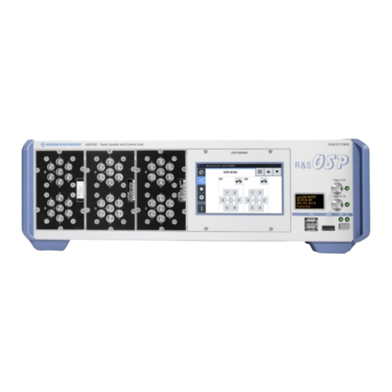
R&S
OSP
Open Switch and Control
Platform
Getting Started
(;ÜÕA2)
1178711702
Version 06
Table of
Contents
Previous
Page
Next
Page
1
2
3
4
5
Advertisement
Table of Contents
Need help?
Do you have a question about the OSP220 and is the answer not in the manual?
Ask a question
Questions and answers
Related Manuals for Rohde & Schwarz OSP220
Laboratory Equipment Rohde & Schwarz R&S OSP Series User Manual
Open switch and control platform (327 pages)
Remote Control Rohde & Schwarz OSP-B200R User Manual
(27 pages)
Control Systems Rohde & Schwarz OSP230 Getting Started
Open switch and control platform (43 pages)
Control Systems Rohde & Schwarz R&S SMM-K553 User Manual
Frontend control (67 pages)
This manual is also suitable for:
Osp230
Osp320
Osp-b200s2
1528.3105.02
1528.3105.03
1528.3111.02
...
Show all
1528.3134.02
1528.3134.04
Table of Contents
Print
Rename the bookmark
Delete bookmark?
Delete from my manuals?
Login
Sign In
OR
Sign in with Facebook
Sign in with Google
Upload manual
Upload from disk
Upload from URL


Need help?
Do you have a question about the OSP220 and is the answer not in the manual?
Questions and answers