Table of Contents
Advertisement
Quick Links
THANK YOU for buying this product. To help ensure it gives complete satisfaction please install it according to these
instructions and then pass the instructions to the appropriate person for retention and future reference.
SAFETY.
This is a mains powered product. It is designed to be installed by suitably qualified personnel only and in
accordance with the applicable building and electrical regulations. Before installation or maintenance the electrical supply to the
product must be isolated.
WARRANTY
This product is warranted to be free of defects in materials, design and workmanship for 5 years from the date
of purchase. If a suspected fault should develop in this time, please call our helpline on +44 (0)800 783 6909. This warranty
does not include batteries or consumable items such as fuses.
INSTALLATION SUPPORT
above We will do our best to help. When reporting a suspected fault or seeking installation support the problem is likely to be
resolved most quickly if you have full product details to-hand, as well as details of when and where it was purchased.
LUMINAIRE INSTALLATION
1.
Remove the front cover by loosening the four
corner screws.
2.
Secure the luminaire in position. If screw
fixing, then this MUST be done using the 4-off
"drill through" fixing points provided in back
face of the base.
Note! Not using these points may result in
the base splitting & the warranty will be
void. It is also the installer's responsibility
to ensure the fixing points are sealed to
maintain the IP65 rating.
3.
Drill the cable entry point on the side wall of the base & fit the cable gland provided, to maintain the IP65 rating.
4.
Route the power supply cable through the cable gland to the terminal block. Terminate ensuring correct polarity is
observed. If required, use the internal cable clamp to secure the mains cable.
5.
Check the mains fuse is fitted correctly in its holder.
6.
Connect the black (negative) wire from the PCB to the battery via the spade connector & ensure the positive (red)
connector is already in position.
7.
Refit the cover to the body.
8.
Rotate & angle the lamp heads to required direction. The bolts/screws on the lamp heads may need to be loosened to
do this – ensure they are re-tightened afterwards to hold position.
9.
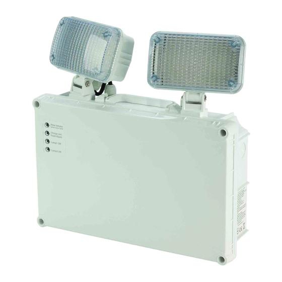
Reconnect the power supply. The green LED's on the front face for "Charge/Fault", "Lamp1 OK" & "Lamp2 OK" should
now illuminate. These indicate the battery is charging & the lamps are healthy. If this does not happen, see section
"Fault Indicators" below. NOTE! The lamps will not illuminate at this point.
10. The batteries should be allowed to charge for at least 24 hours before carrying out a full discharge test to check
batteries are charging correctly & the maintained duration is being achieved.
FAULT INDICATORS
Faults on the product will be indicated both visually by the LED display on the front face & audibly via an internal sounder:
Battery – If there is a battery failure or it is not connected properly, the "Charge/Fault" LED will flash & the sounder will
•
give off a one beep cycle (beep – beep – beep ...). The flash & beep will be in sync.
Lamp – If there is a lamp failure or it is not connected properly, the "Lamp1" or "Lamp2" LED will go out, the
•
"Charge/Fault" LED will flash & the sounder will give off a two beep cycle (beep beep – beep beep – beep beep...). The
flashes & beeps will be in sync.
Operation time failure during auto-test – If the during the automatic duration test (every 90 days) the duration time
•
of one hour is not met, the "Charge/Fault" LED will flash & the sounder will give off a three beep cycle (beep beep beep
– beep beep beep – beep beep beep...). The flashes & beeps will be in sync.
OPERATION / MAINTENANCE
1.
Nominal battery life is 4 years, after which time they should be replaced with a suitable equivalent.
2.
This luminaire MUST be disconnected before the circuit it is installed on is subjected to any high voltage or insulation
resistance testing, otherwise irreparable damage will occur to luminaire components.
3.
Ensure cleanliness of luminaires is maintained so as not to affect performance.
4.
If required, the sounder can be disconnected by unplugging the small 2-pin connector on the internal PCB.
EMERGENCY TWINSPOT INSTRUCTIONS
st
Issue 02 1
If installation advice or accessories are required please also contact us on the number
December 2016
Advertisement
Table of Contents

Related Manuals for Newlec EMERGENCY TWINSPOT


Summary of Contents for Newlec EMERGENCY TWINSPOT
- Page 1 EMERGENCY TWINSPOT INSTRUCTIONS Issue 02 1 December 2016 THANK YOU for buying this product. To help ensure it gives complete satisfaction please install it according to these instructions and then pass the instructions to the appropriate person for retention and future reference.
- Page 2 SELF-TEST FUNCTION This product comes with a built in self-test facility. Once given a permanent mains supply, the luminaire will automatically carry out a monthly functional check & an annual full duration test (in line with the testing procedures listed below to BS 5266). Each fitting is set to start this sequence of testing at random times, so all the luminaires will not be tested at the same time.
Need help?
Do you have a question about the EMERGENCY TWINSPOT and is the answer not in the manual?
Questions and answers