Table of Contents
Advertisement
Quick Links
Vibco
inStrUction manUal
WARNING: Failure to read and follow these installation instructions and safety precautions could result in personal injury, equipment damage,
shortened service life or unsatisfactory equipment performance. All information in this document is vital to the proper installation and operation of
the equipment. It is important that all personnel who will be coming in contact with this product thoroughly read and understand this manual.
vibco makes brackets for mounting vibrators on a variety of concrete forms
Most commonly used models shown here. Specialty brackets for most types of forms are available.
Consult VIBCO for more information regarding proper bracket models and placement.
Wedge
Head
Wide
Wedge
Wedge
Pocket
Pocket
Bracket model numbers vary with vibrator model ordered
start
1
thank you for choosing
a vibco vibrator!
ADDITIONAL DETAILS AVAILABLE ONLINE AT www.vibco.com
vibrator placement
3
For coarse materials: mount
vibrator 1/3 of the distance
from the discharge opening to
the top of the sloped portion of
the bin.
For fine materials: mount
vibrator 1/4 of the distance
from the discharge to the top of
the sloped portion of the bin.
FOR CONCRETE FORM MOUNTS
refer to the Concrete Handbook
online at www.vibco.com or call 800-633-0032
mounting hardware
5
A MOUNTING PLATE MUST BE USED
to ensure proper stability for the vibrator.
Orientation of the mounting plate depends
on number
2 BOLT
of mounting
holes of the
vibrator.
Determine
4 BOLT
number of
mounting
holes and
orient as
shown here.
standard
studded
800-633-0032 for Mounting Plates & Brackets, Spare & Replacement Parts and 24/7 technical Support
bolting procedure
7
step 1
Place vibrator on mounting
plate, then insert
& tighten
1
2 Grade
5 bolts
2
on same
end of
vibrator.
See proper
torque values right.
800-633-0032 • vibrators@vibco.com • www.vibco.com
Wide
Clamp
Wedge
on Bracket
Head
mounting instructions checklist
2
̸
Determine vibrator placement on equipment.
̸
Determine length of channel iron and style of mounting plate.
̸
STITCH
weld mounting plate or bracket to channel iron.
̸
STITCH
weld channel iron to bin or form system.
̸
Attach vibrator to mounting plate. Check the mounting plate for warping &
shim if necessary. DO NOT OVER TIGHTEN THE BOLTS.
̸
Install safety chain or cable.
̸
Connect wiring for vibrator using the NEC Standards.
̸
Take a voltage reading while vibrator is running.
̸
Take an amperage reading while vibrator is running.
̸
FILL OUT WARRANTY CARD AND MAIL TO VIBCO!!!!
NO!
UNIT SHOULD
PERPENDICULAR
OF CHANNEL,
IT MAY CAUSE
FLExING & THE
VIBRATOR WILL
YES!
NOTE: SHIMMING THE FEET IS NECESSARY TO AVOID STRAIN ON THE SHAFT &
BEARINGS THAT CAN CAUSE HIGH AMPERAGE DRAW & BURN OUT THE VIBRATOR.
MAx
step 2
GRADE 5
TORQUE
BOLT SIZE
ft-lbs
Now, look at feet on
other end of vibrator.
1/4"
9
If a gap exists
5/16"
18
between the mounting
3/8"
32
plate & foot, welding
warped the mounting
1/2"
78
plate. Shim space
For other bolt grades,
under feet.
please consult VIBCO.
Wood
Form Bracket
plates & channel selection
4
VIBRATOR
MNTNG PLATE
CHANNEL IRON SIZE
FORCE in LBS
THICKNESS
3" x 4.1 lbs
101 - 500
1/4" - 3/8"
3" x 5 lbs
4" x 5.4 lbs
501- 1200
1/2"
4" x 7.5 lbs
1201 - 3000
5/8"
6" x 8.2 lbs / 6" x 10.5 lbs
1)
Longer channel iron will not affect vibrator performance,
total channel length should not exceed length of bin wall.
2)
Percentages shown indicate % of bin wall height your channel iron should be for
shorter bins.
3)
To match your vibrator on chart above, model number suffixes generally correspond to
pounds of force generated. For any questions, consult VIBCO.
stitch weld
6
BE SURE ALL WELDING
IS DONE By A CERTIFIED
WELDER. ALL STANDARD
OVERALL
LENGTH OF
CHANNEL AND PLATES
VIBRATORY
PROVIDED By VIBCO
ARE A36 STEEL, 304
ALWAYS BE
STAINLESS OR
6061 ALUMINUM.
TO LENGTH
DO NOT MOUNT
OTHERWISE
VIBRATOR
DIRECTLY
TO SURFACE OF BIN !!!
Always use mounting
OVERLOAD &
plate & channel iron
BURN OUT.
SHIM
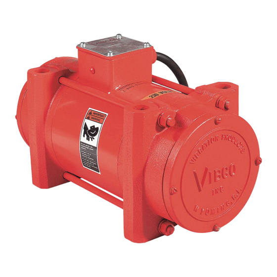
US High Frequency
Electric Vibrators
For septic tanks, manholes, culverts and
other precast forms, ask for VIBCO's
Handbook & Equipment Guide for
External Concrete Vibrators.
For columns, wall forms, tunnels and
other cast-in-place forms, ask for
VIBCO's Handbook & Equipment
Guide for External Vibration of
Cast-in-Place.
BIN WALL
FACTOR
FACTOR
THICKNESS
B
A
1/8" (10 ga.)
2
6
or less
3
1/8" - 1/4"
5
1/4" - 3/8"
4
4
3/8" - 1/2"
3
1/2" & up
2
(TOP VIEW)
ALWAyS WELD
CHANNEL UNDER
(BOTTOM VIEW)
PLATE AREA
3
After gap has been filled with
shim(s), insert & tighten the
other TWO Grade 5 bolts.
USE
FACTOR
CH. IRON
A + B
LENGTH
11
N/A
6 - 8 FT.
10
(80 - 90%)
5 - 7 FT.
9
(70 -80%)
4 - 6 FT.
8
(60 - 70%)
3 - 5 FT.
7
(50 - 60%)
2 - 4 FT.
6
(50 - 60%)
1 - 2 FT.
5
(50 - 60%)
4
N/A
STITCH WELDS
SHOULD START
& STOP 1" (2.5cm)
FROM BOTH ENDS
OF CHANNEL
TO PREVENT
CRACKING
STITCH
WELDS
SHOULD
BE 3" LONG
LEAVING
3" (7.5cm)
BETWEEN
EACH WELD
4
step 3
REV086-13
Advertisement
Table of Contents

Related Manuals for VIBCO US


Summary of Contents for VIBCO US
- Page 1 It is important that all personnel who will be coming in contact with this product thoroughly read and understand this manual. vibco makes brackets for mounting vibrators on a variety of concrete forms Most commonly used models shown here. Specialty brackets for most types of forms are available.
- Page 2 Warranty All warranty claims must be submitted to VIBCO for approval prior to any repairs being done. Failure to do so will void any and all warranty coverage. All repairs will be done at the VIBCO factory. Errors, Shortages & Complaints Complaints concerning goods received or errors should be made at once.
Need help?
Do you have a question about the US and is the answer not in the manual?
Questions and answers